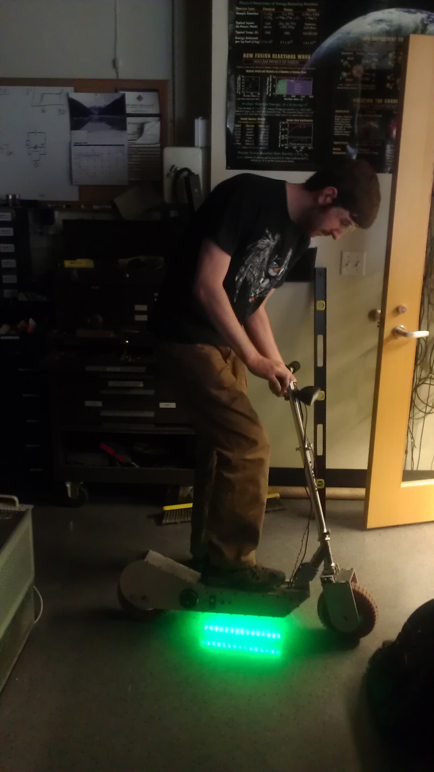
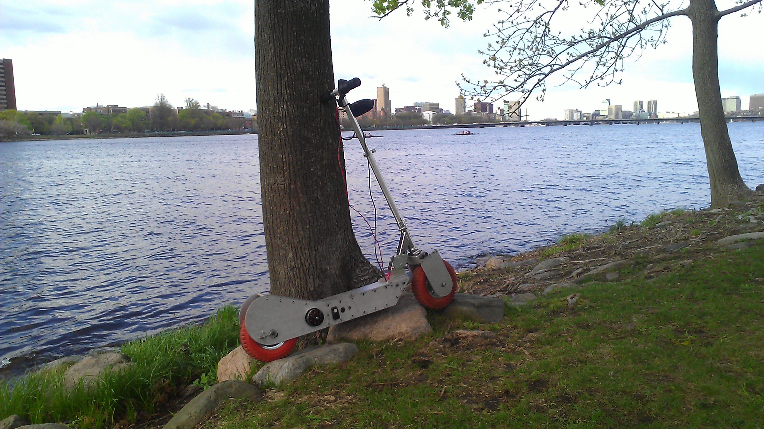
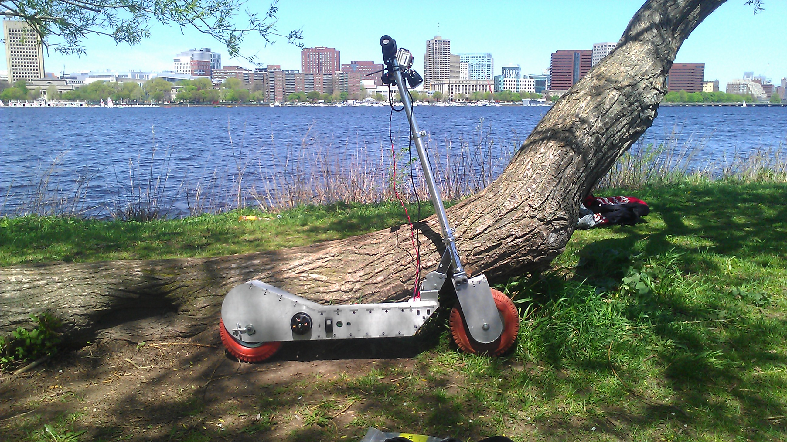
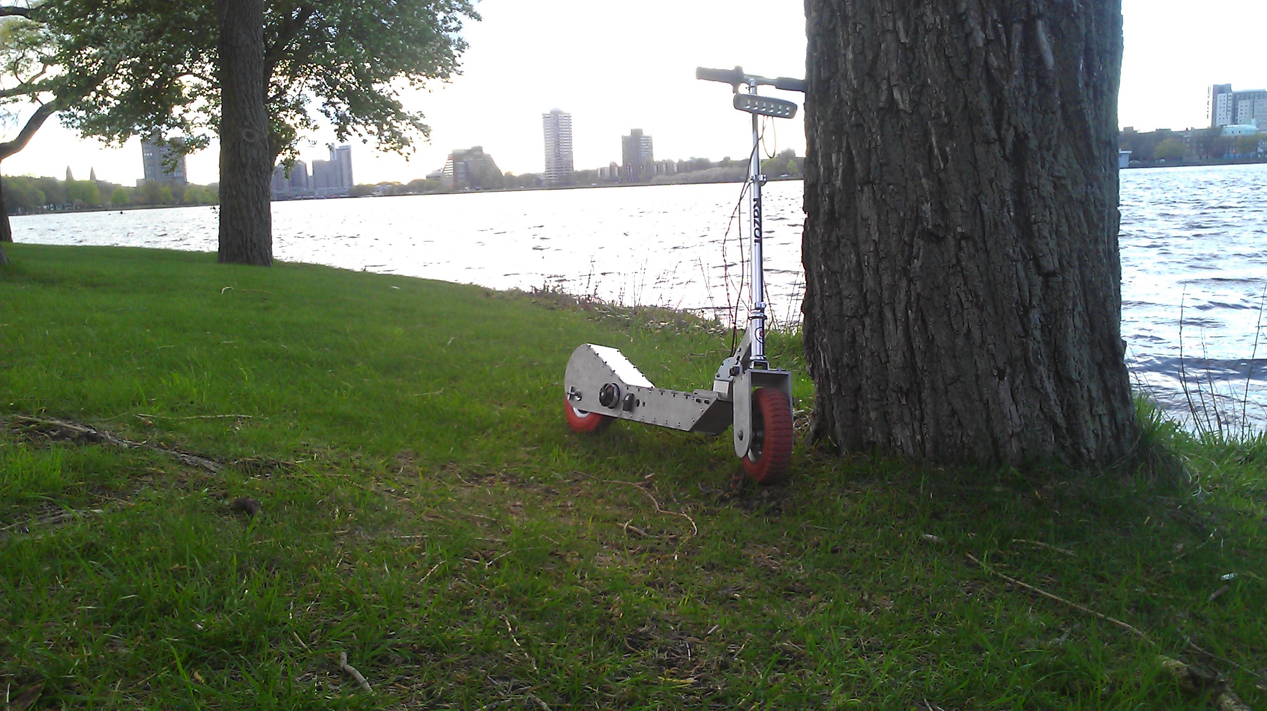
[Fall '12] The Hopper: A Personal City Transportation Vehicle
Description of Project
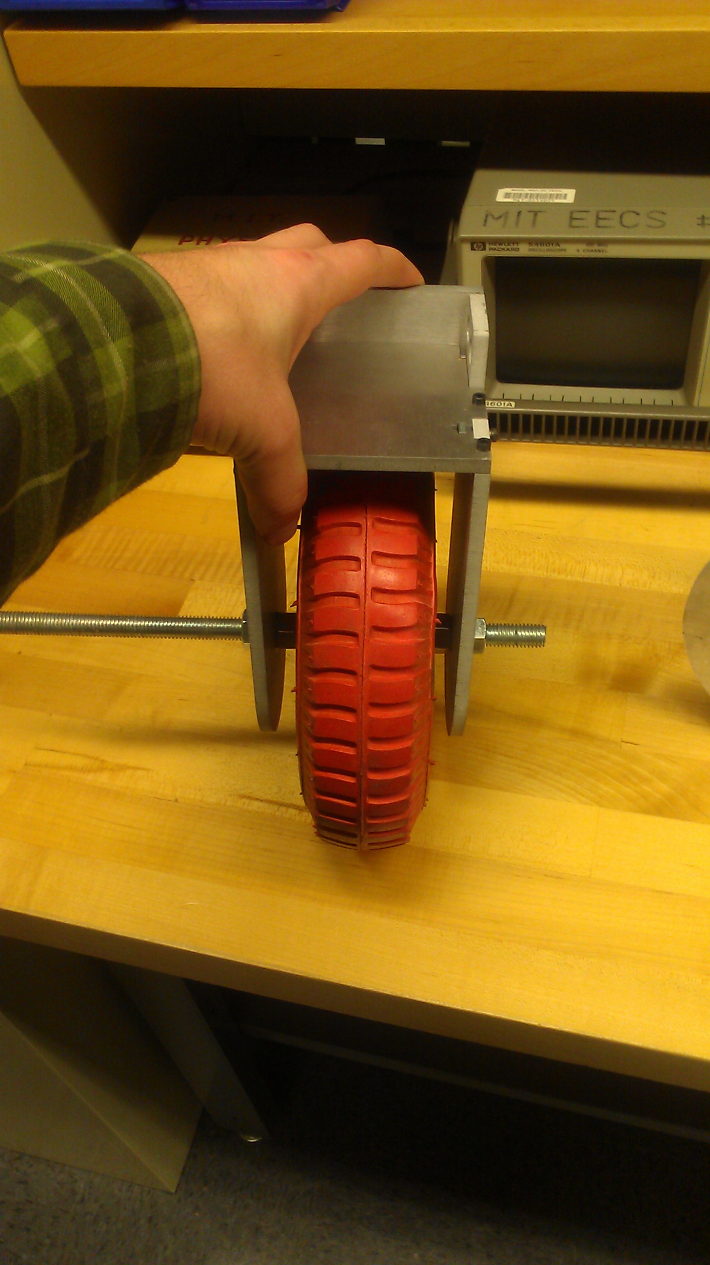
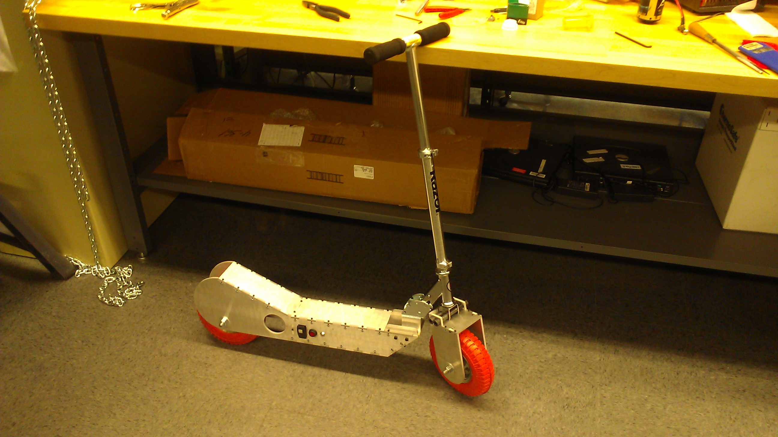
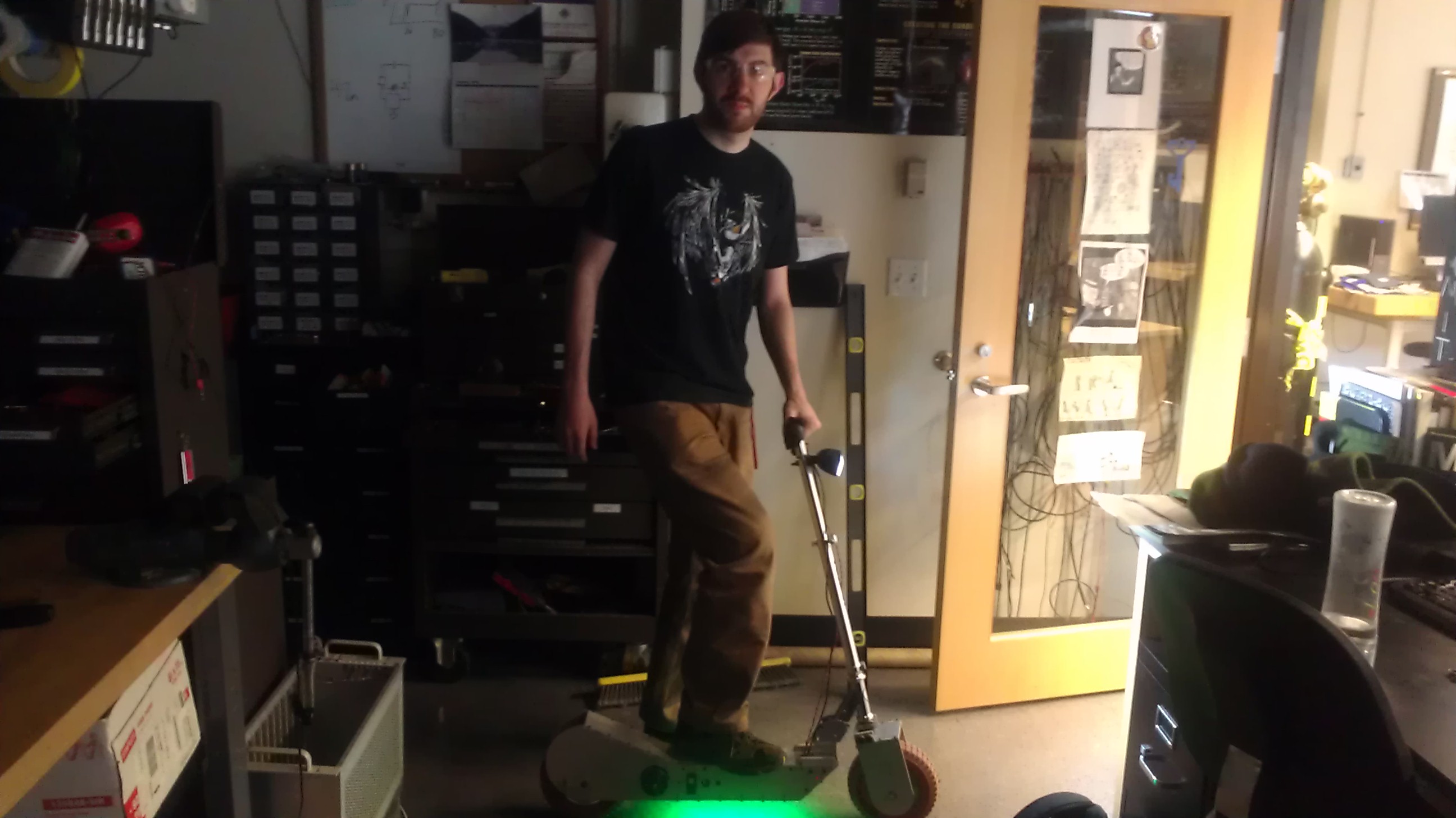
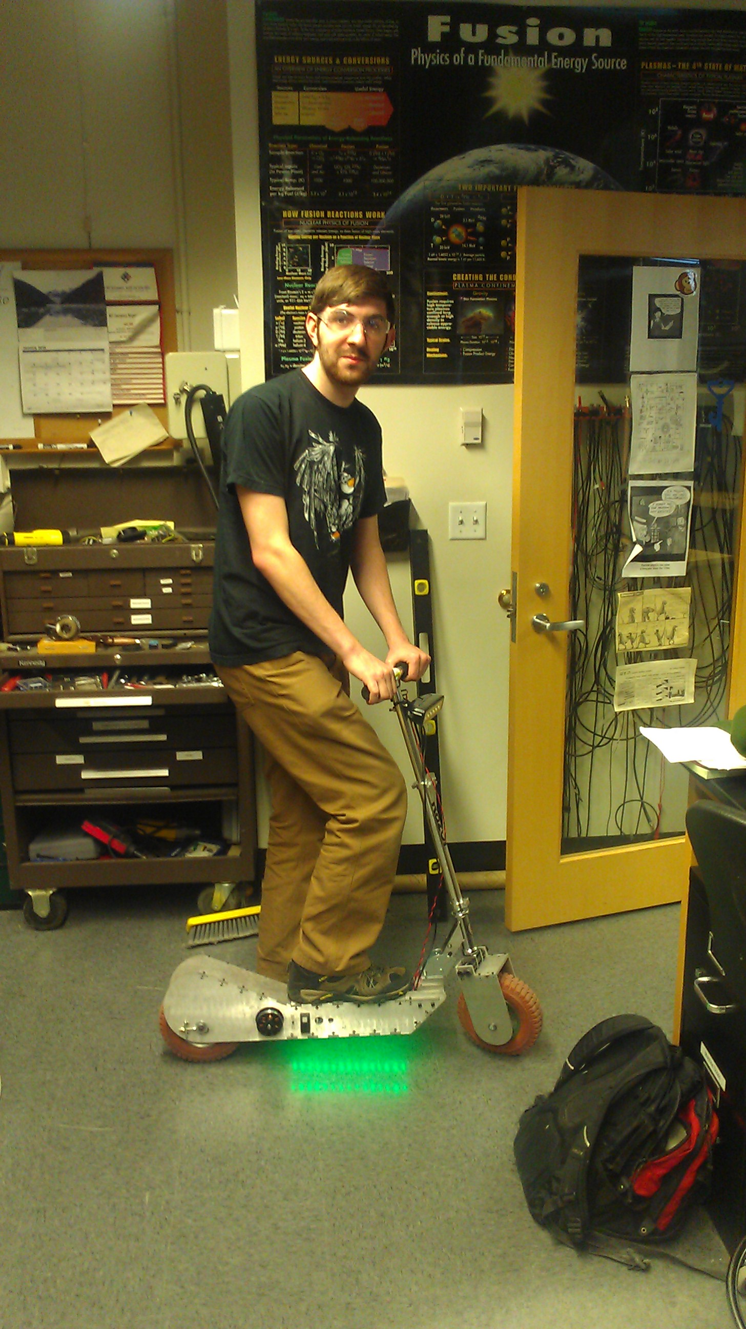
A personal city transportation vehicle, A.K.A. The Hopper. This vehicle aims at being aversatilescooter that can ride both on un-kept roads, and in-doors. The current specs for this vehicle will be; 8inch diameter wheels, Capped speed of ~20mph (Currently capped by motor controller), and an average distance of ~6.4 miles per charge (or pack).
Processes Applied:


Summary:
Design
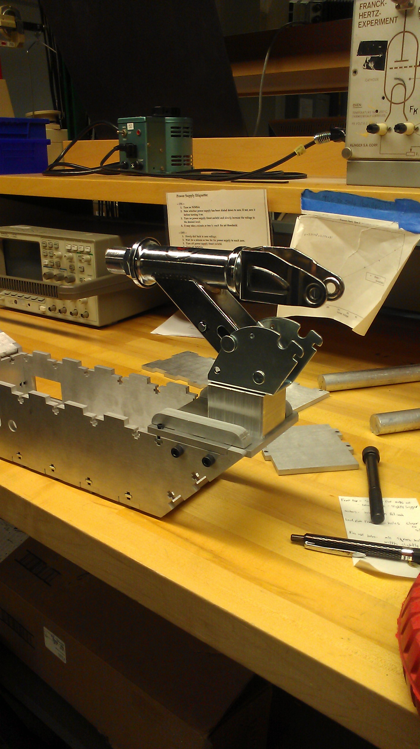
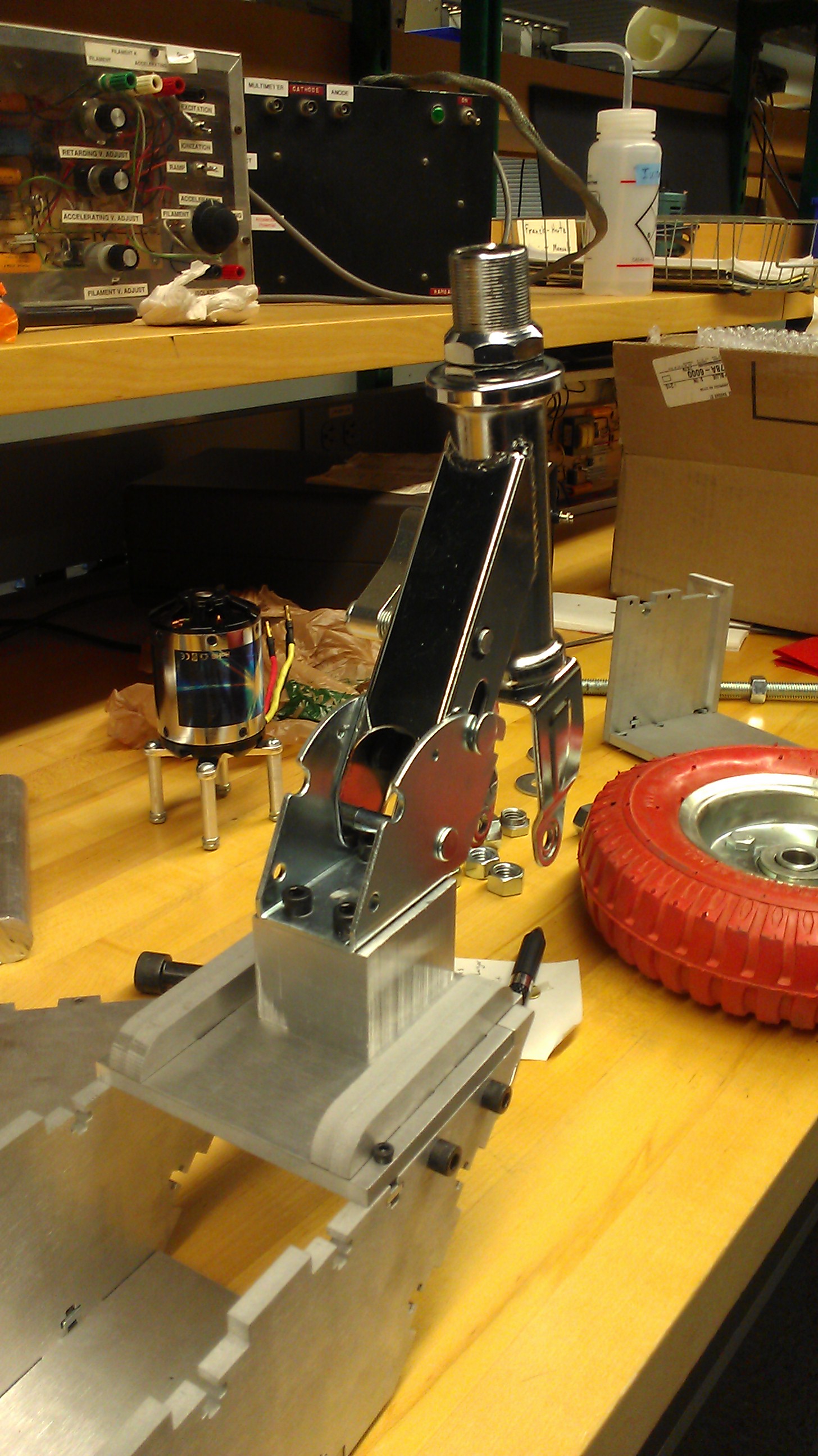
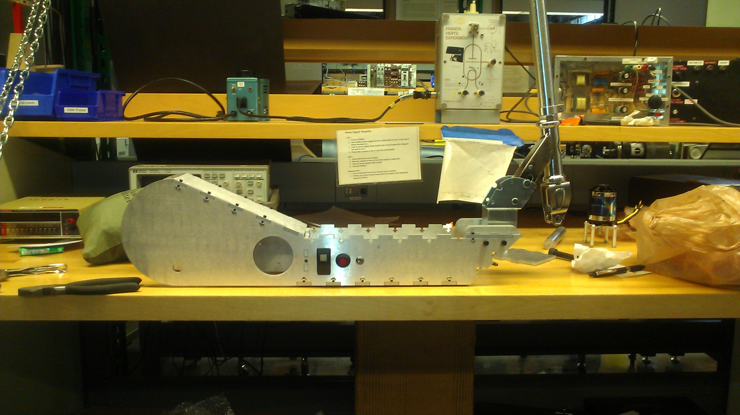
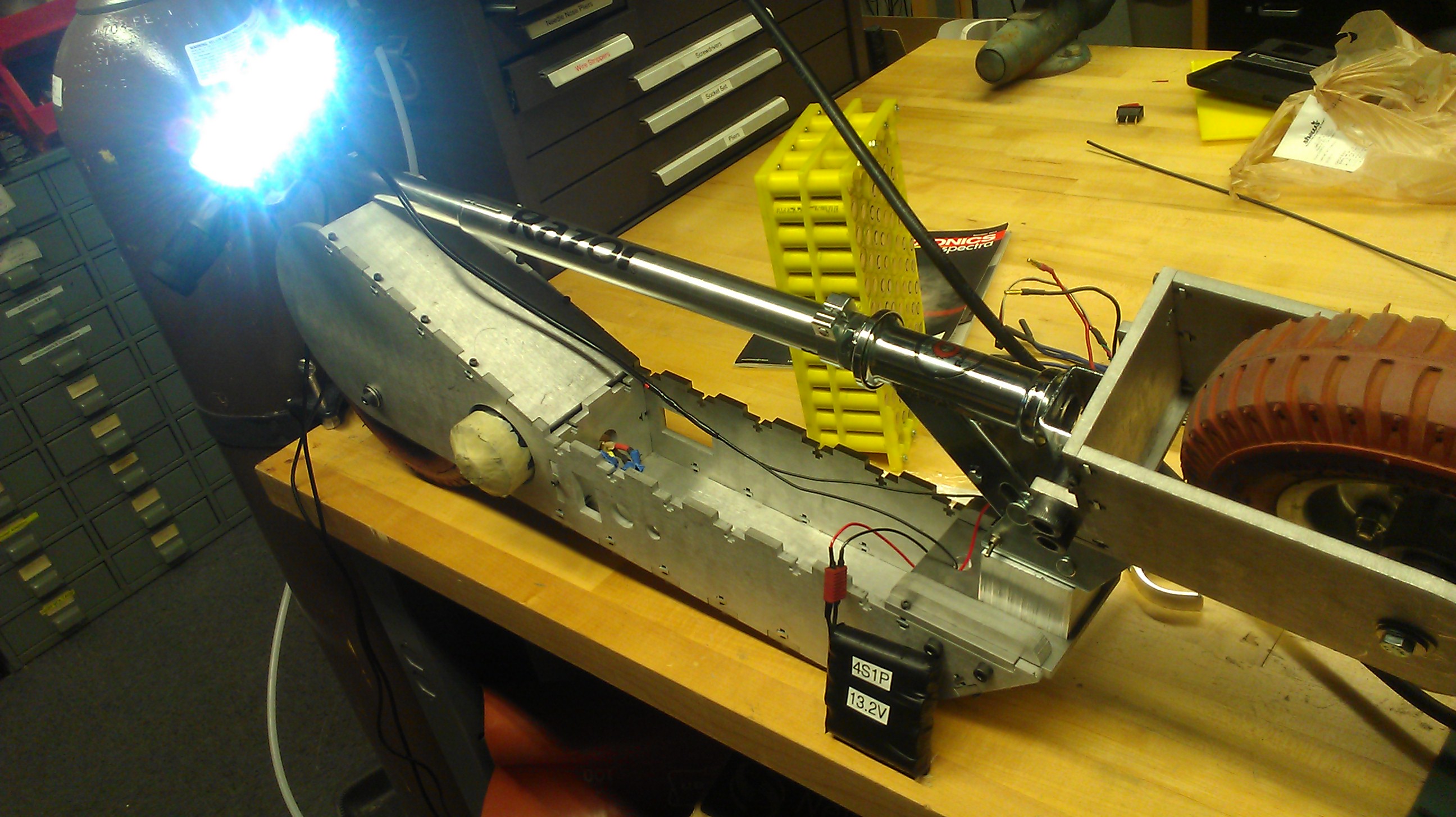
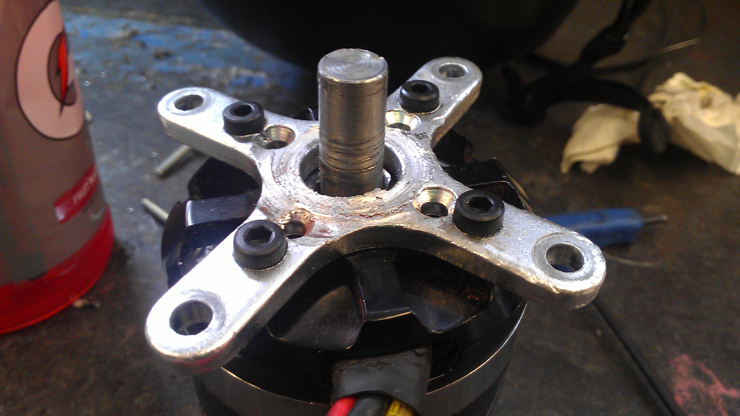
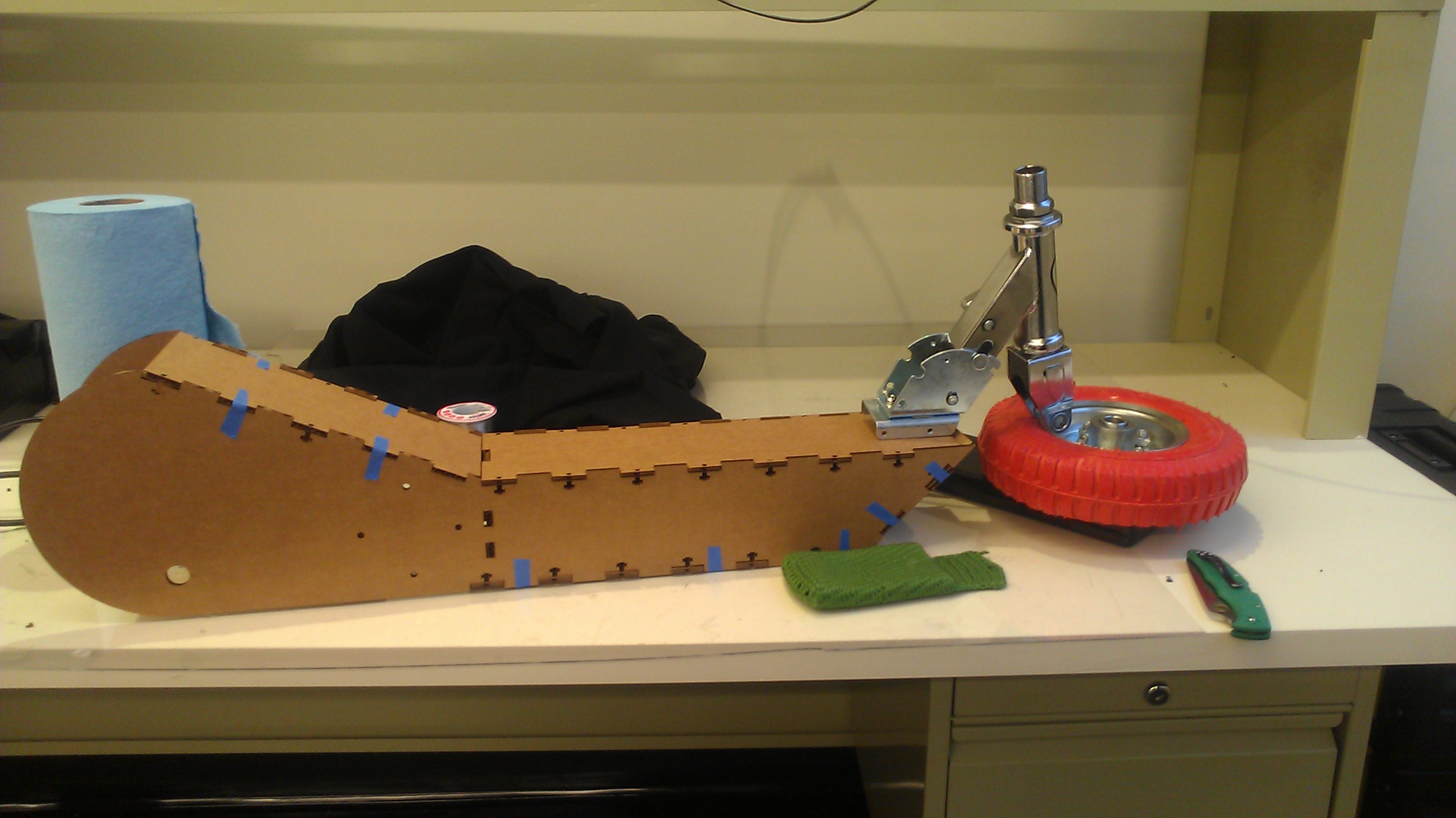
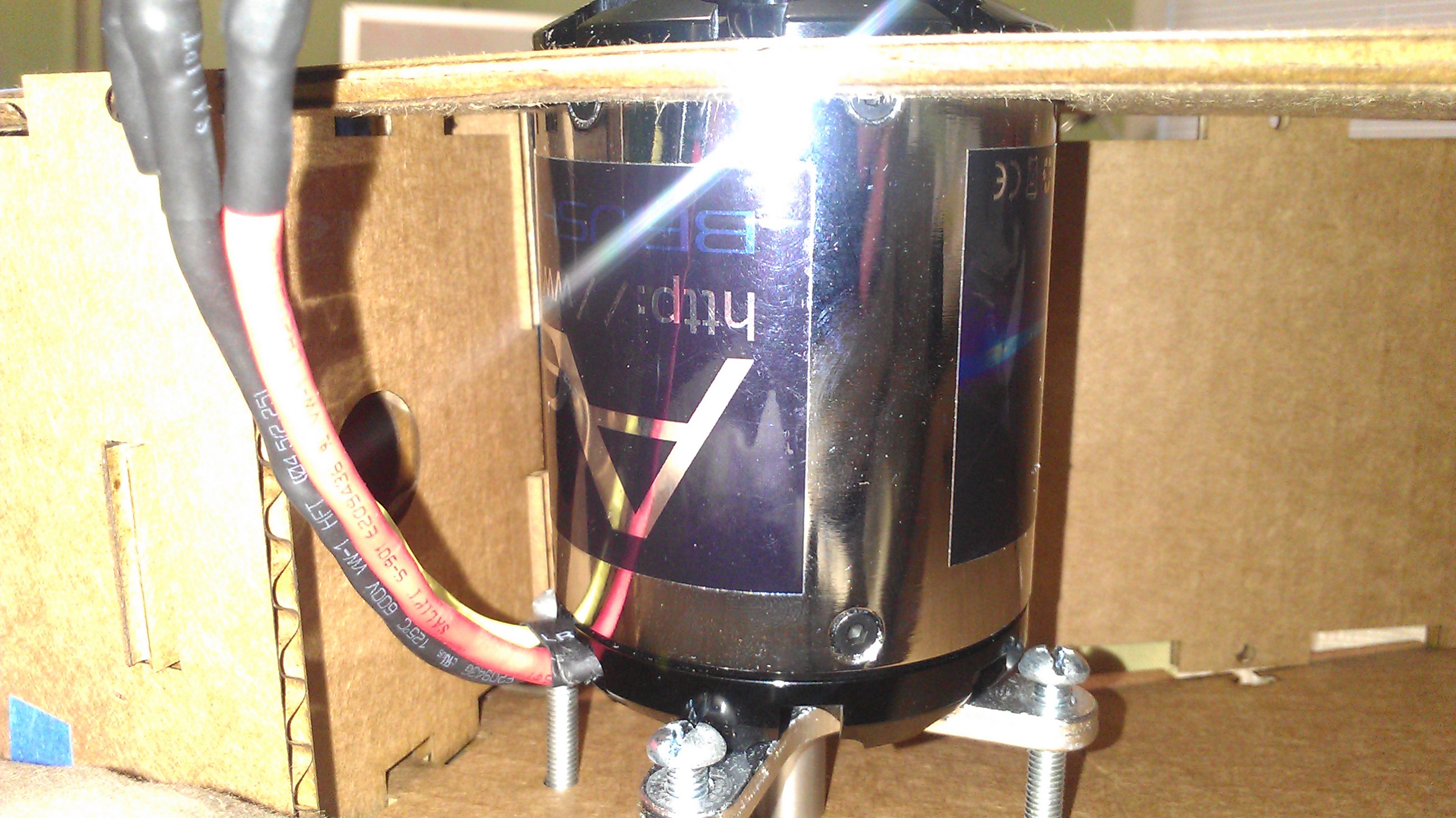
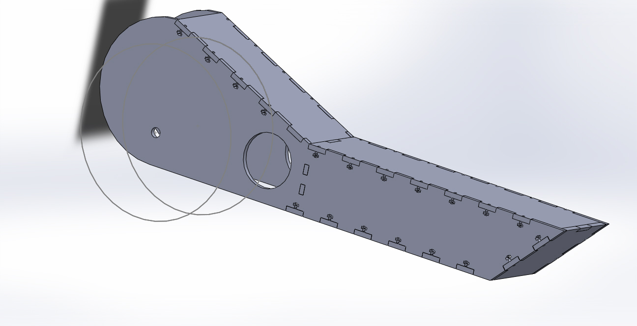
To design this electric scooter I used Solidworks which is provided by MIT. The first major step was to create a design specification sheet, which was used to determine the requirements of the design. Overall, the specifications were as follows: Top Speed ~20mph, durable, Able to deal with pot-holes of Boston, and the ability to disassemble the frame (reduce need for welding Aluminium). With this spec sheet in hand, I went about acquiringthe fixed components for this vehicle which comprised of: Razor scooter front fork, front and back wheels, electrical switches, the motor, and motor controller. This is important in the design phase because it allows me to design the frame around the components that I will end up using, as well as design around my self imposed specifications.
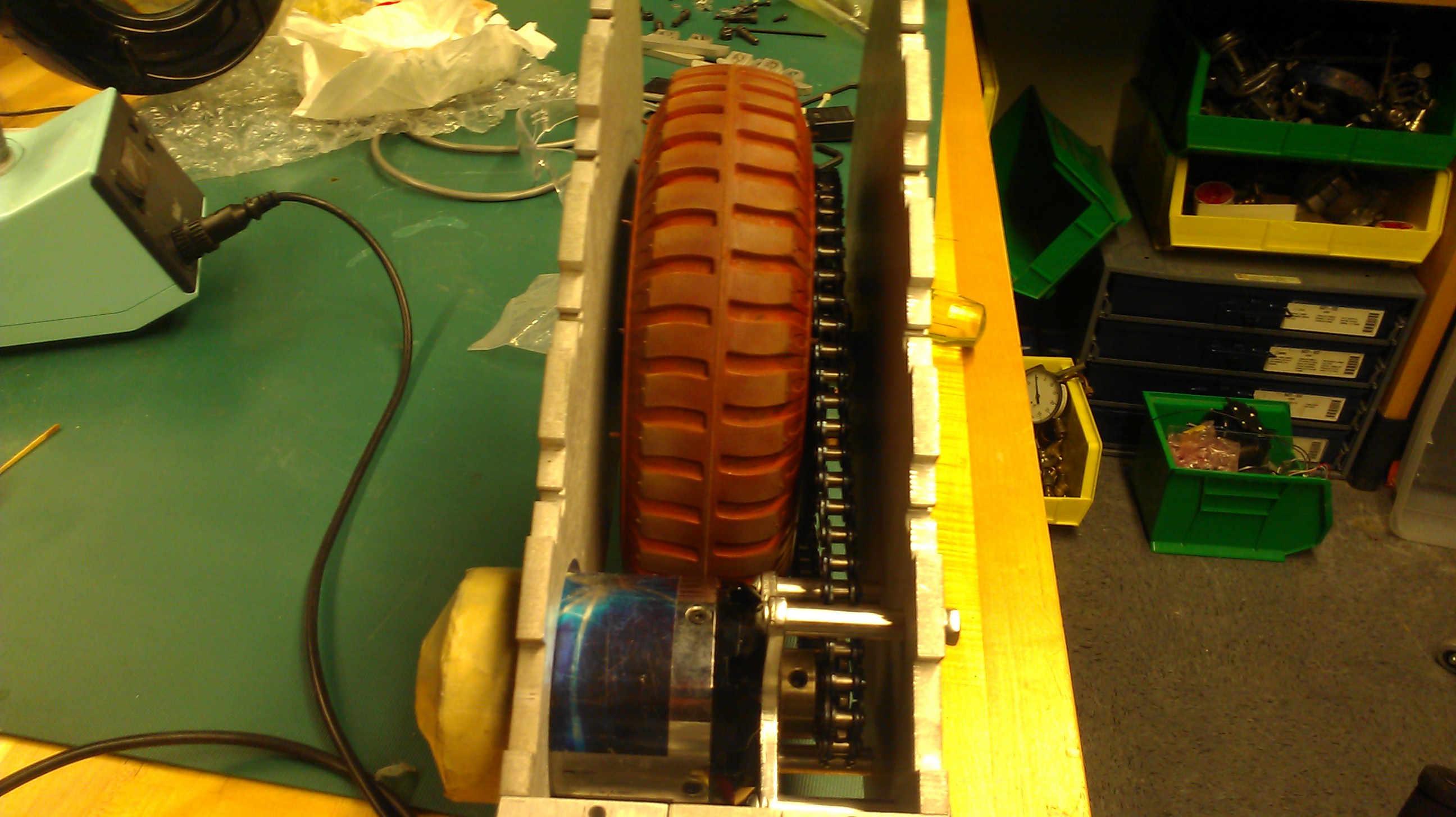
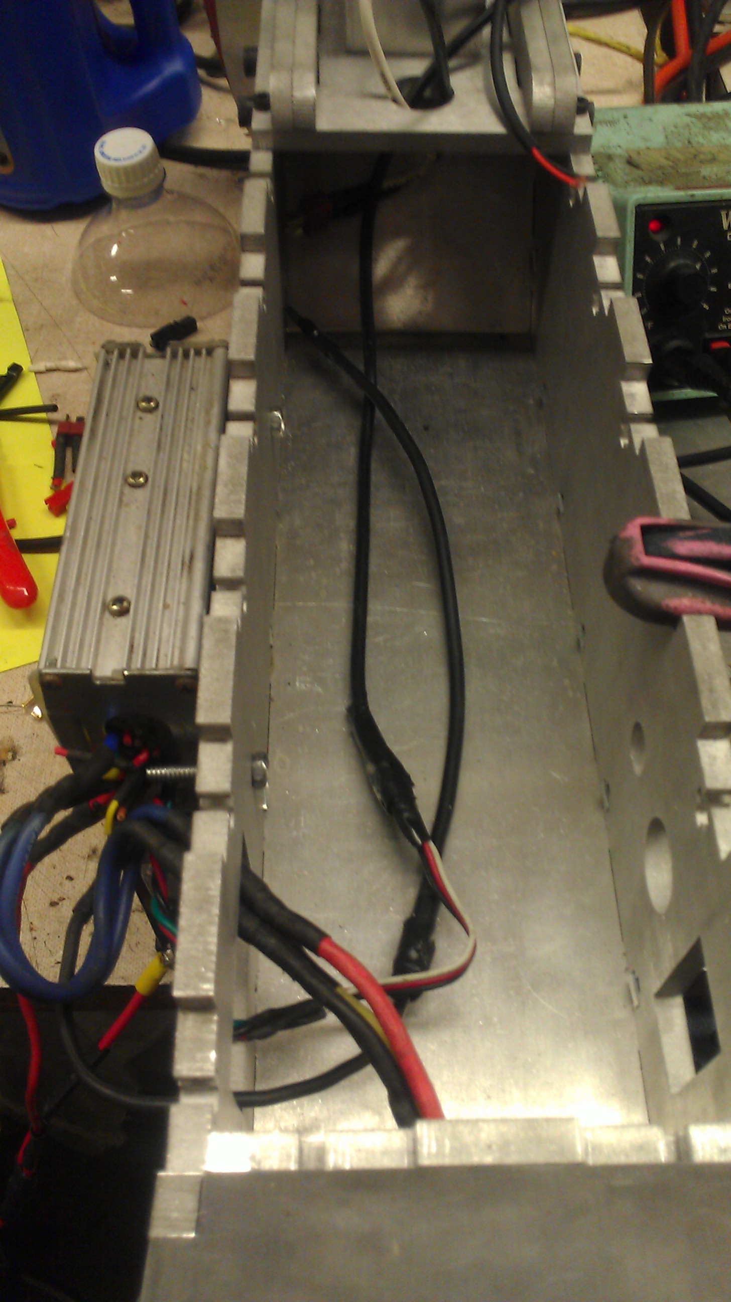
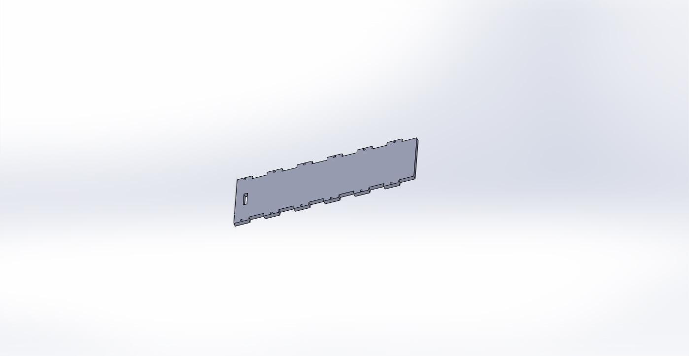
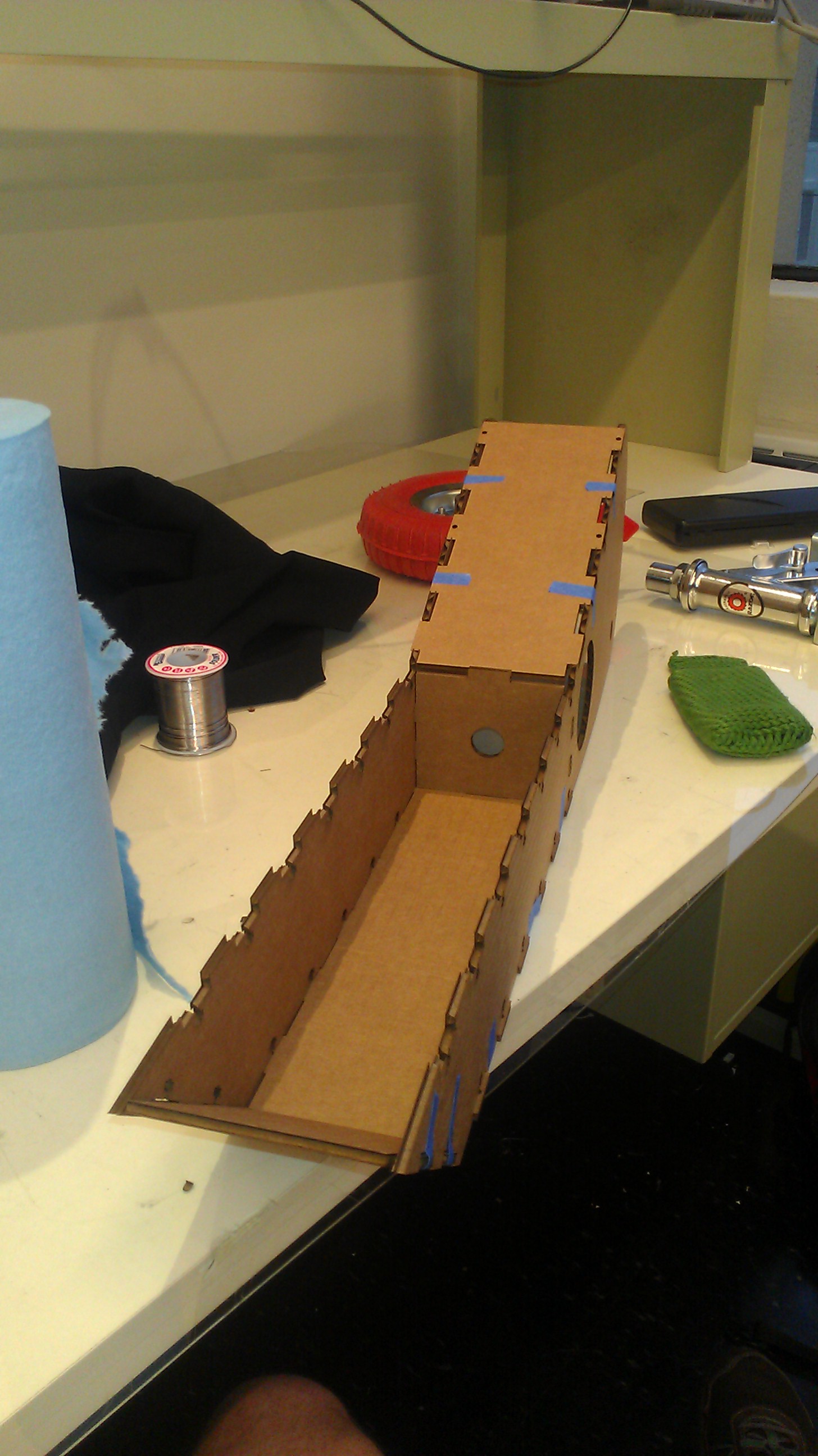
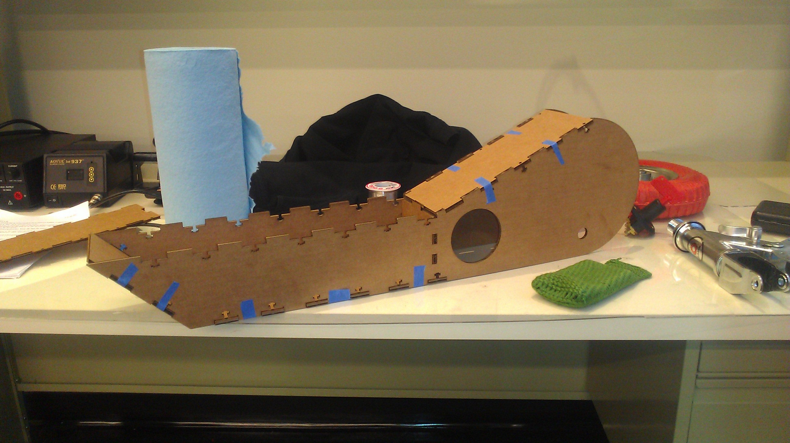
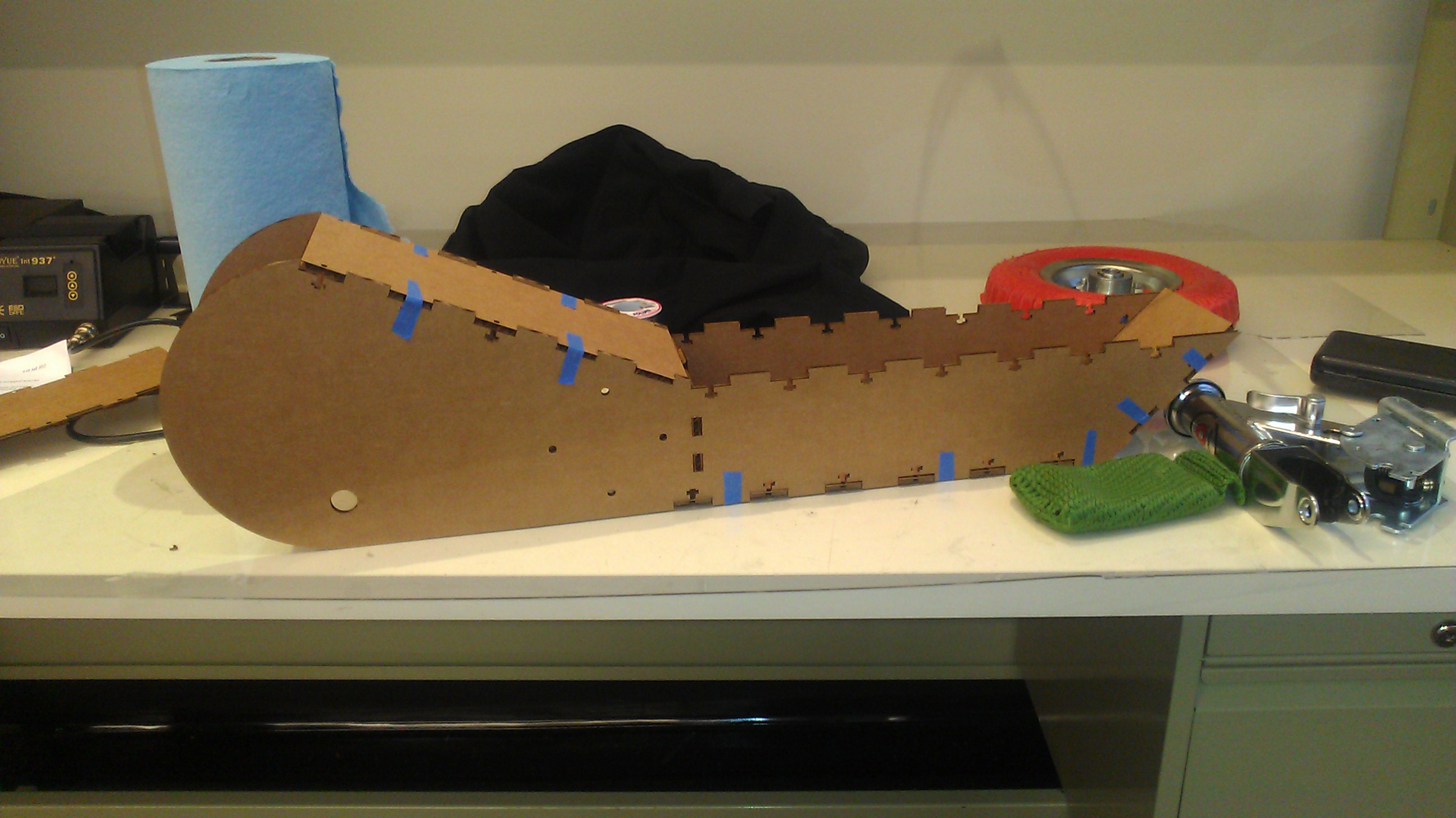
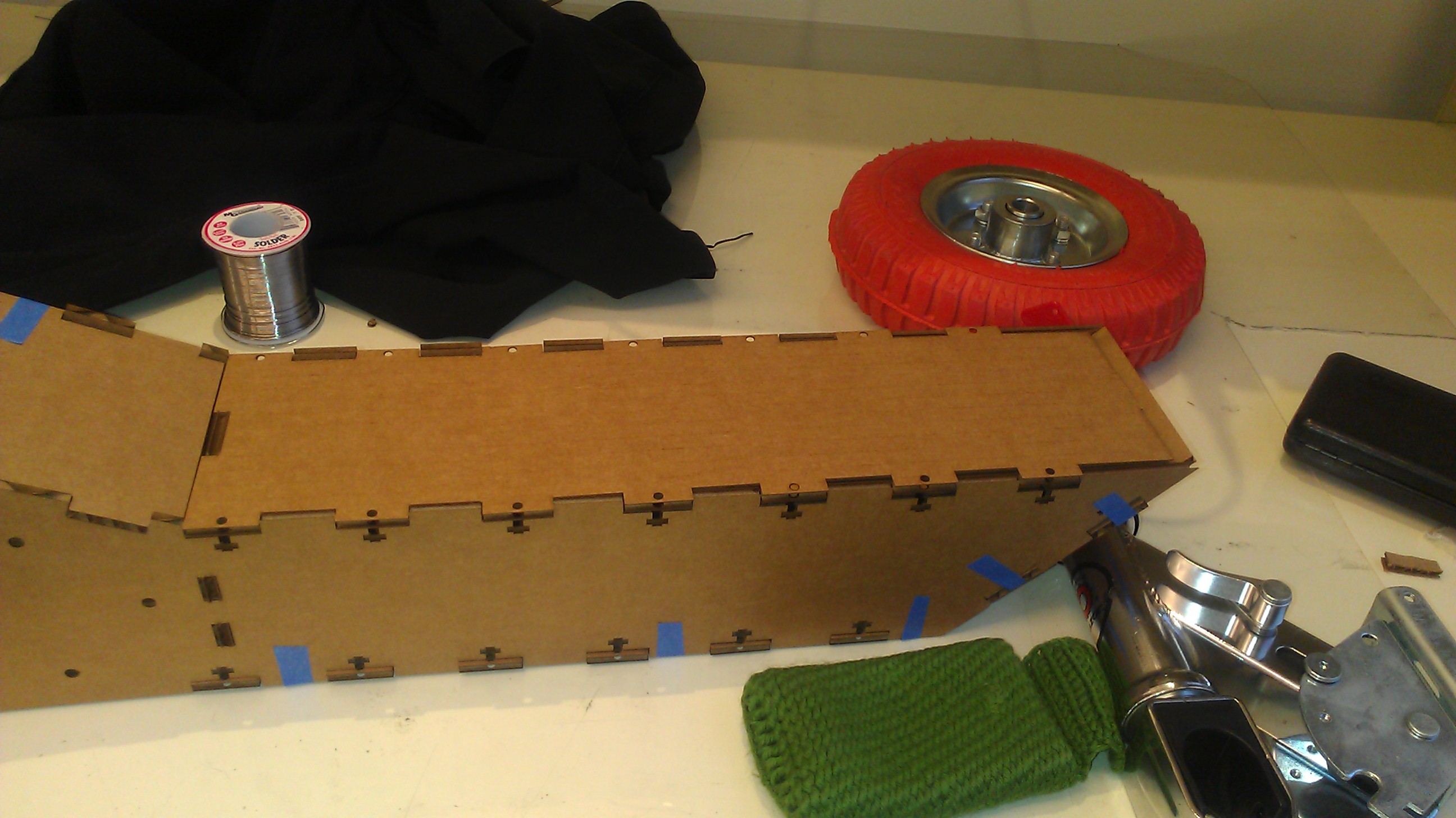
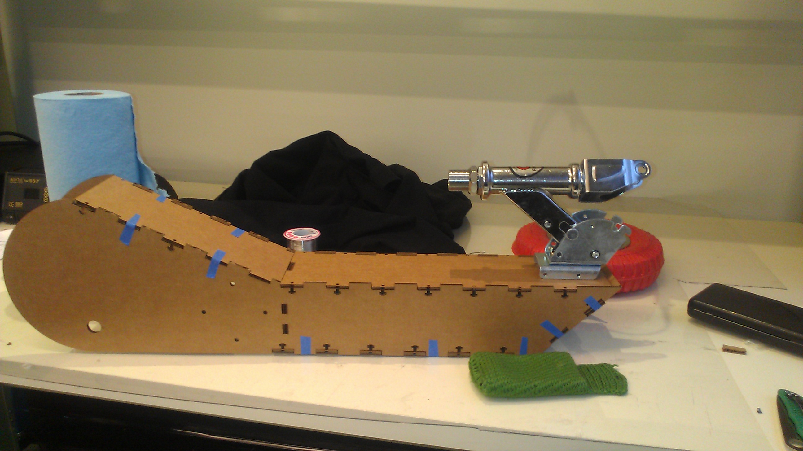
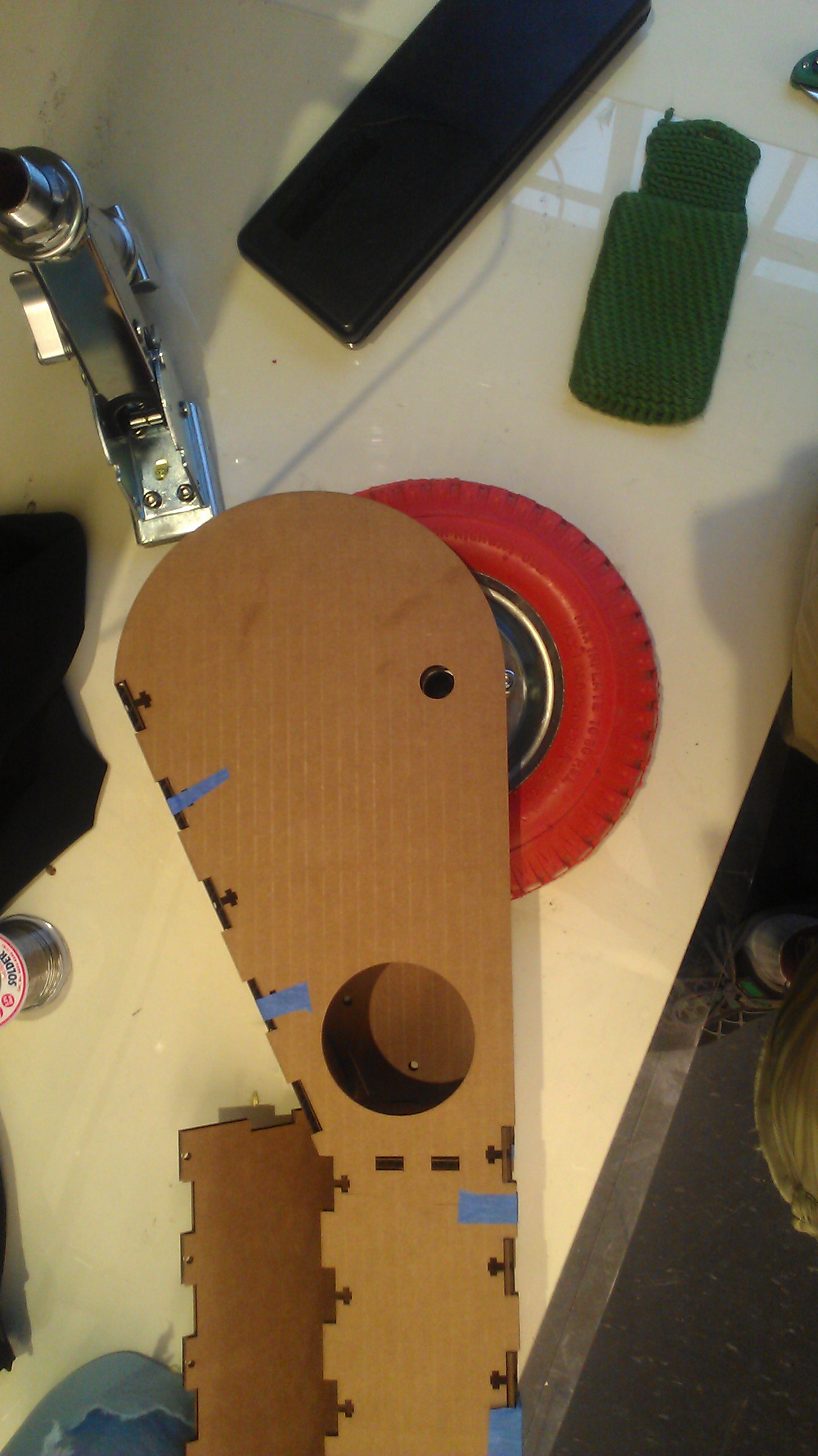
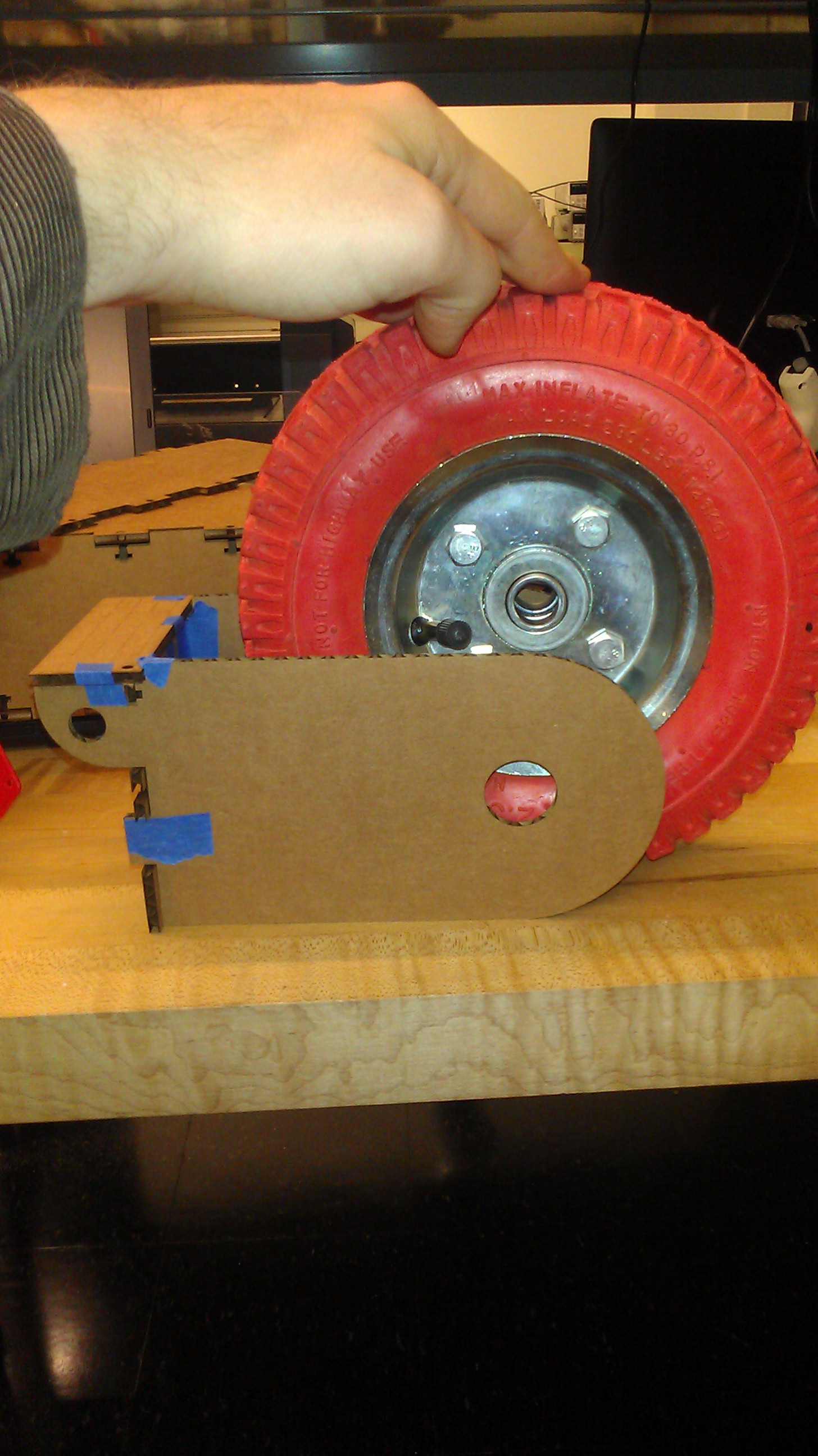
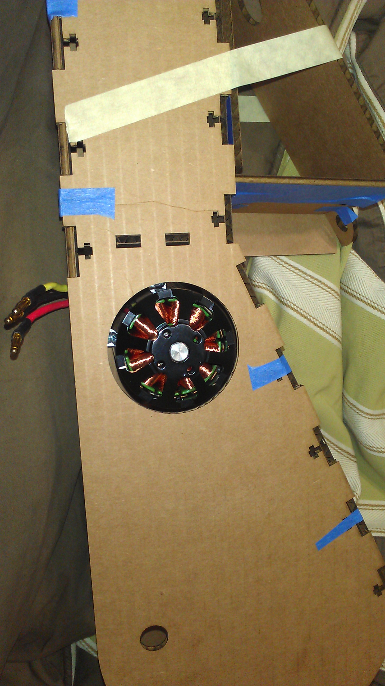
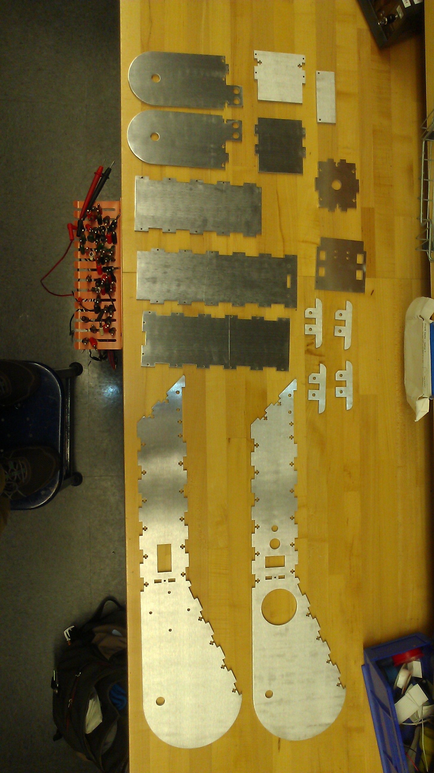
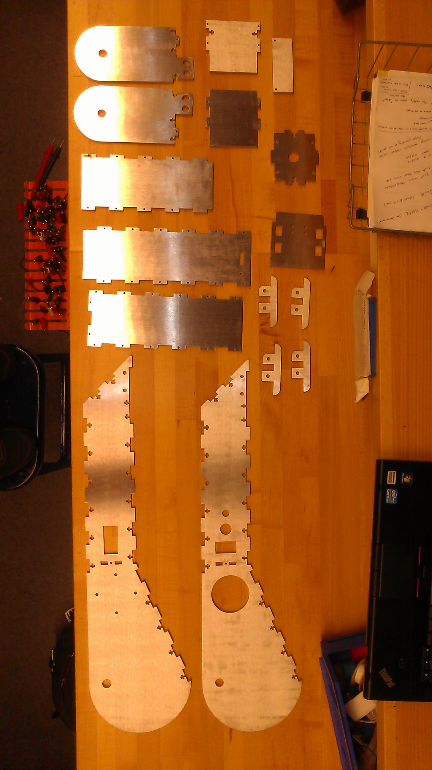
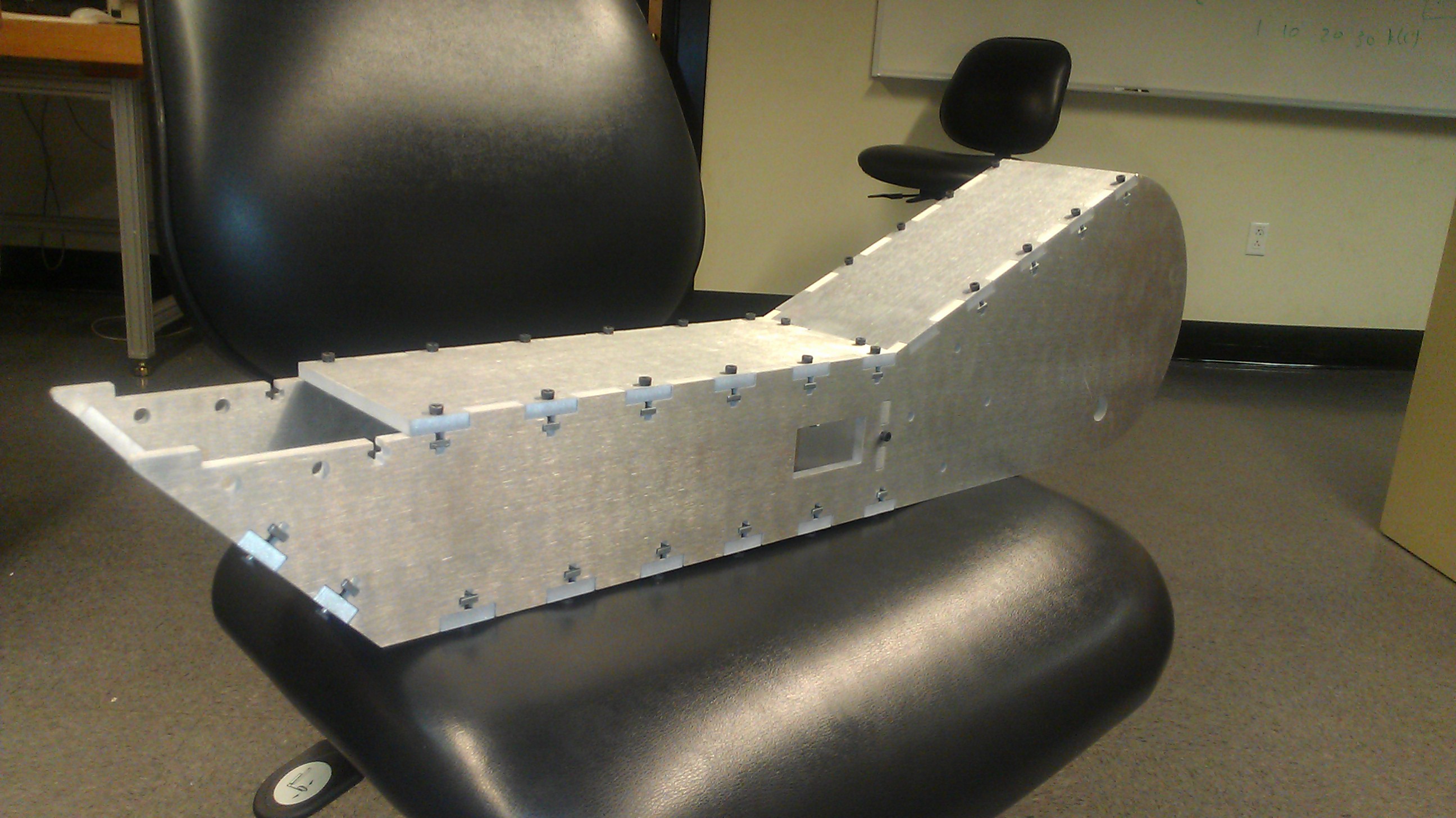
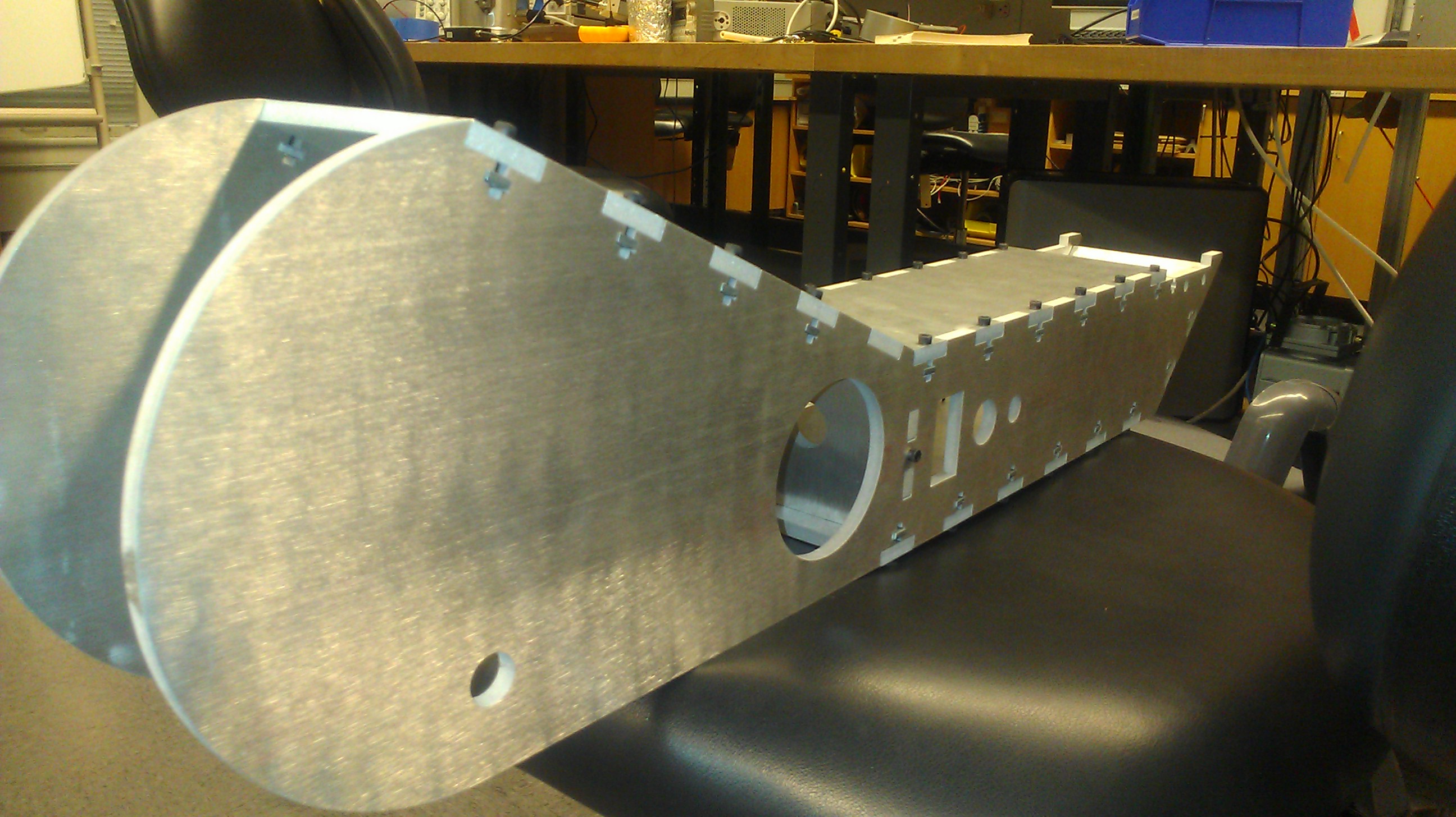
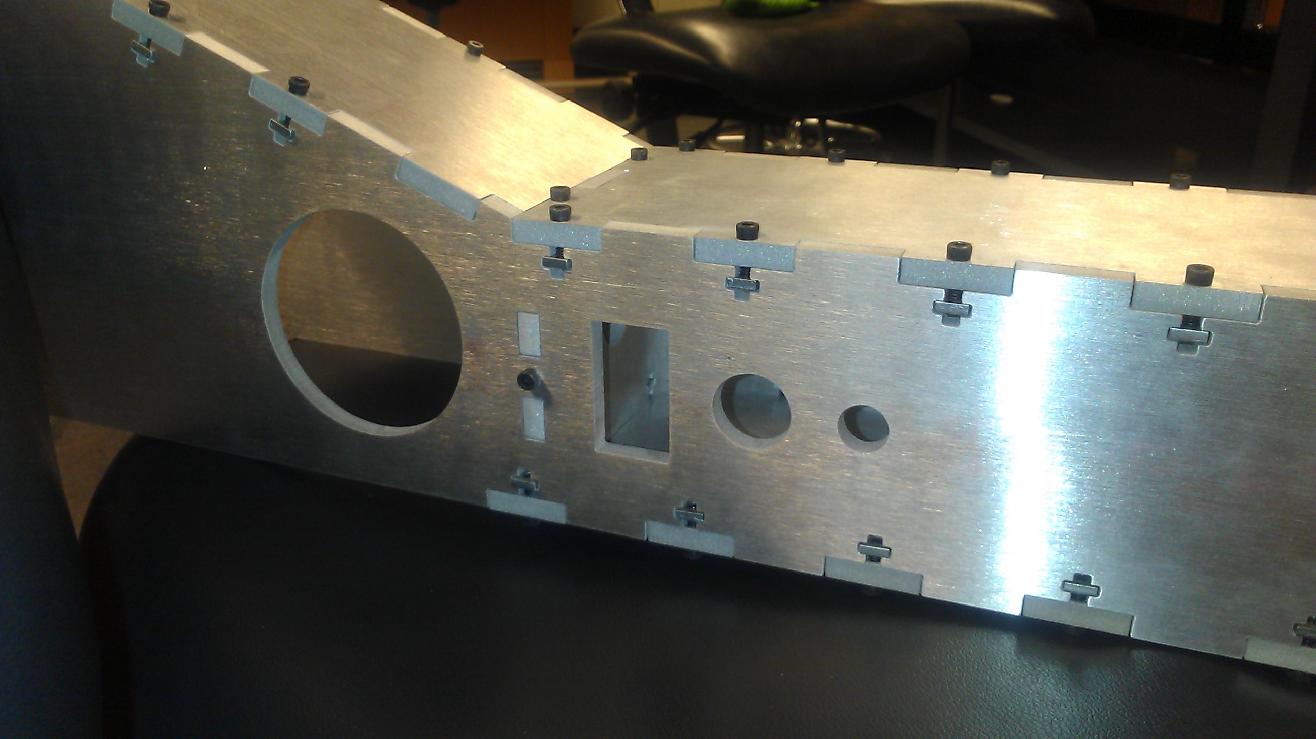
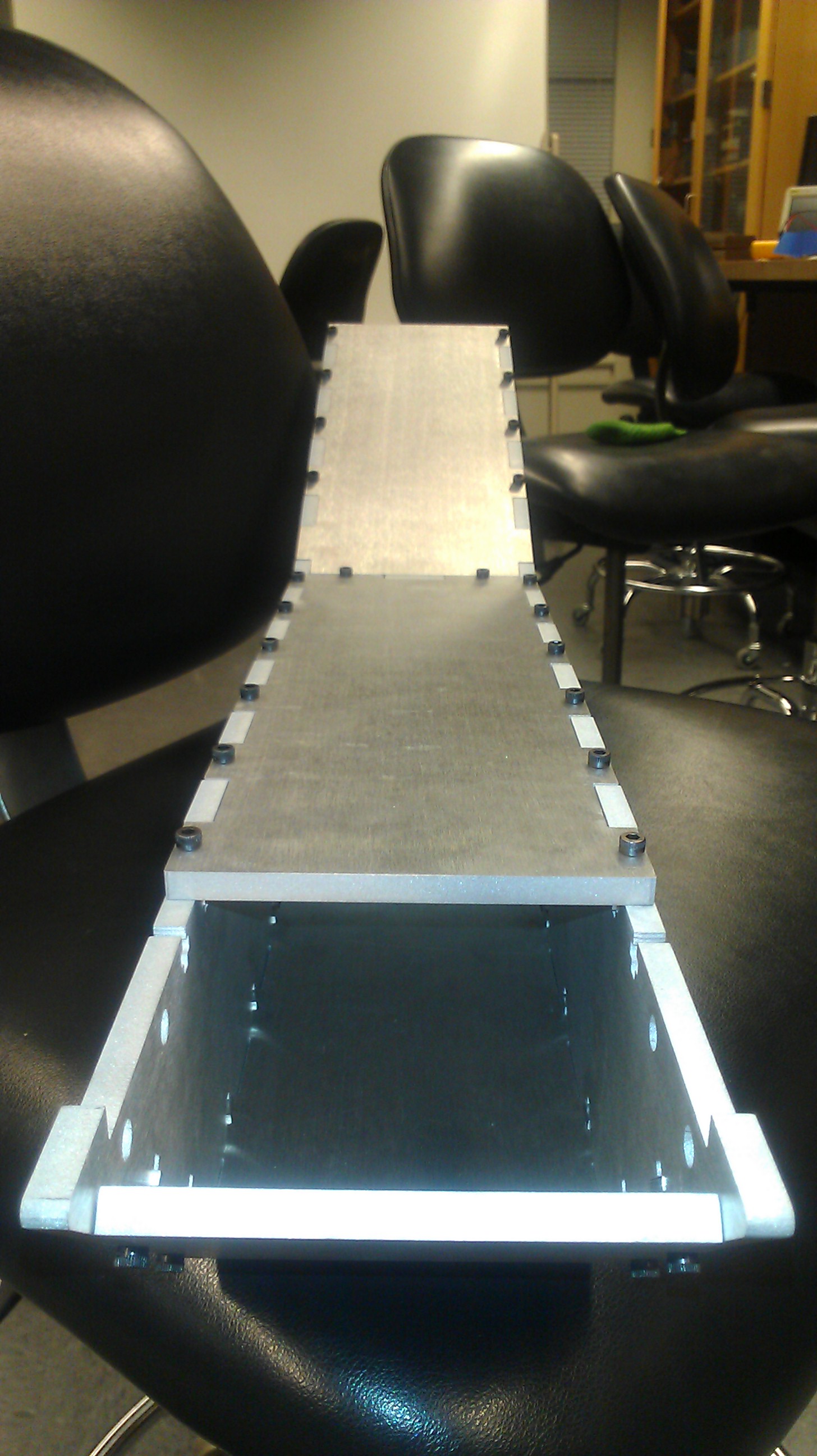
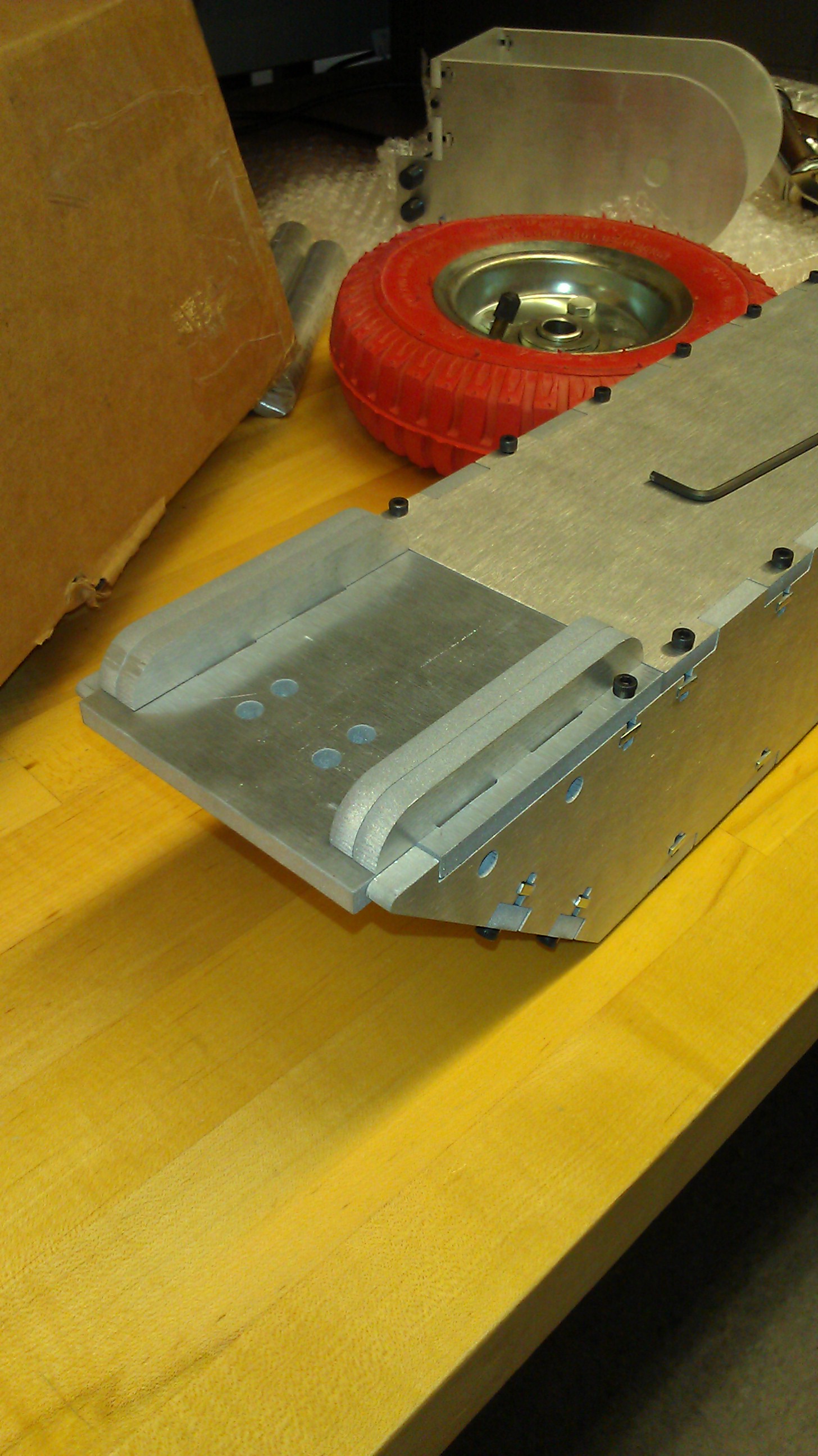
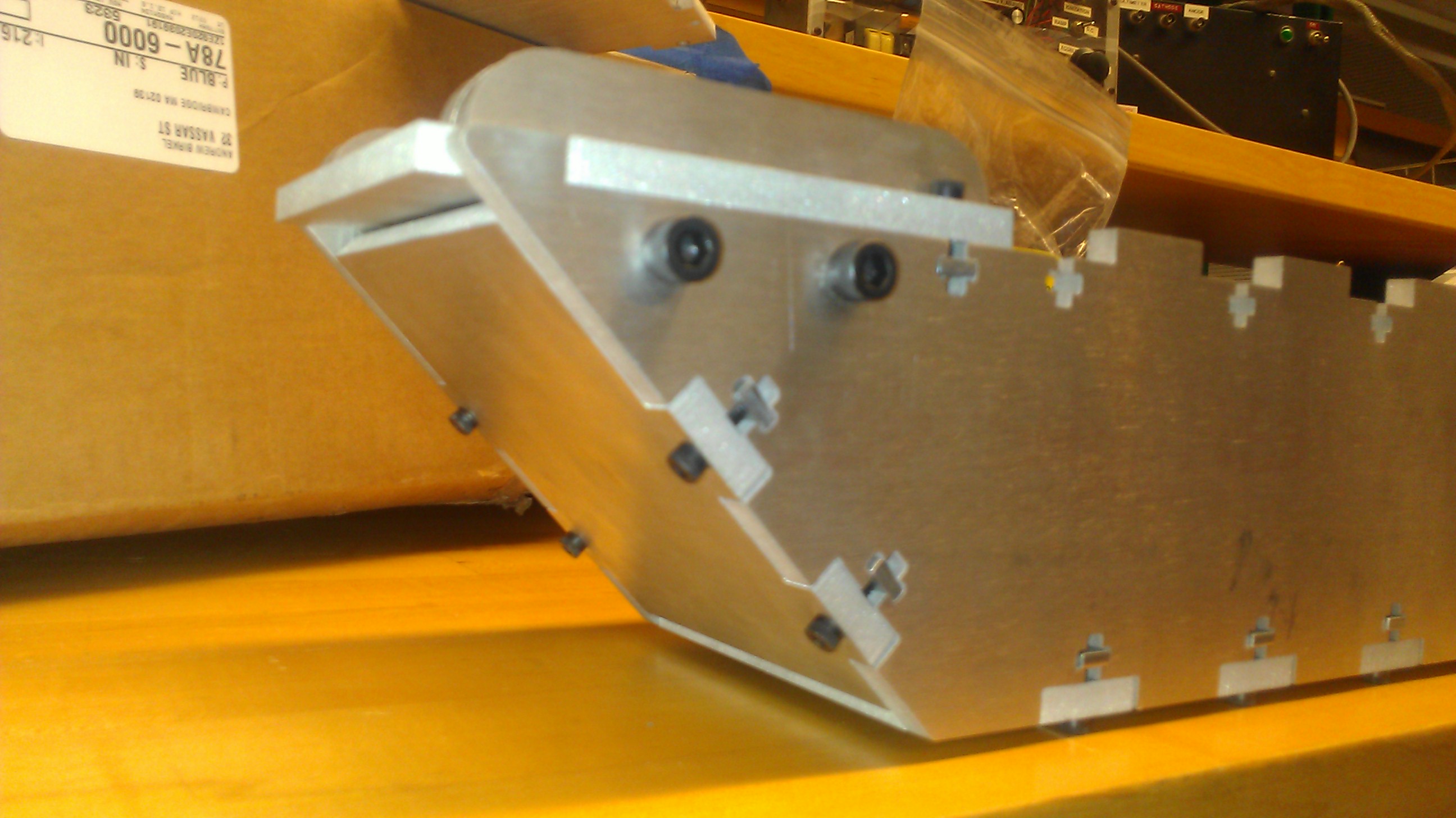
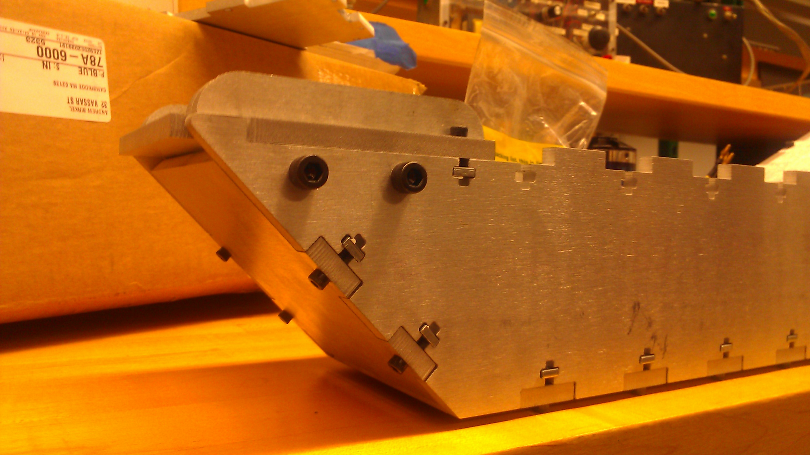
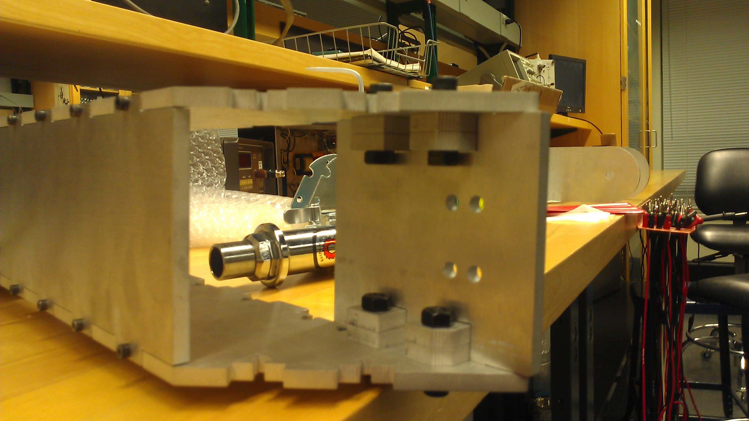
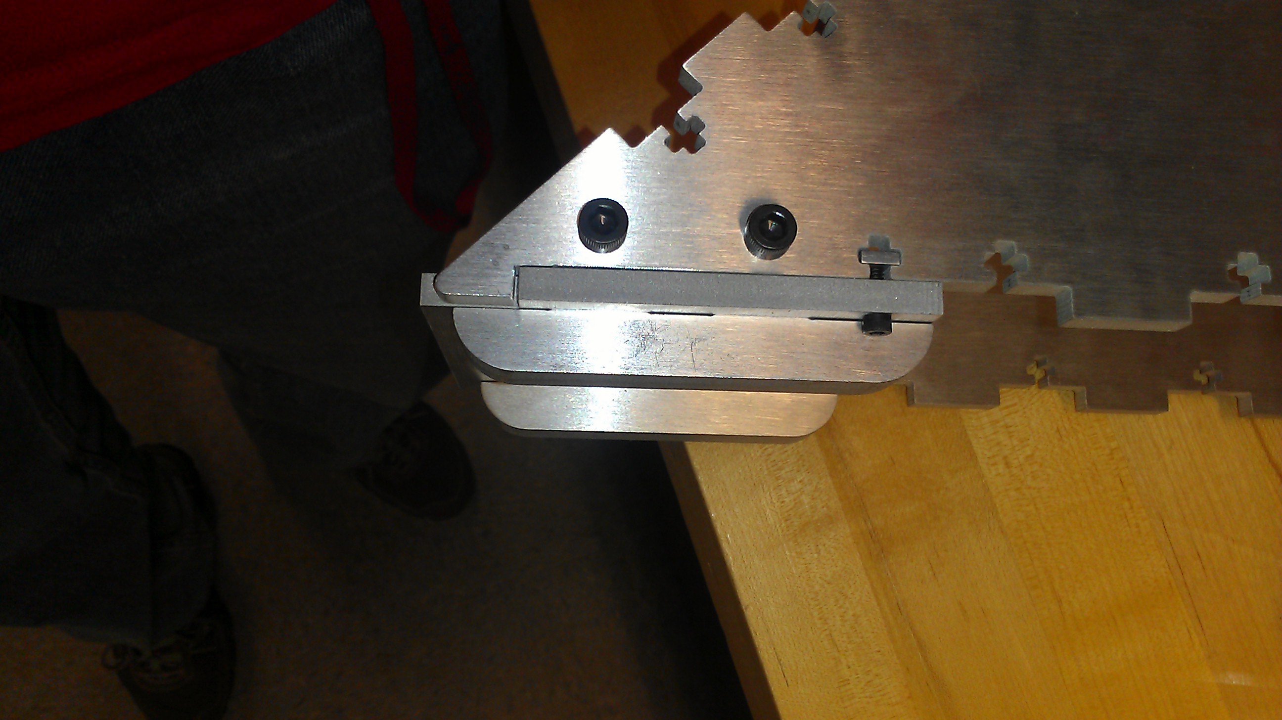
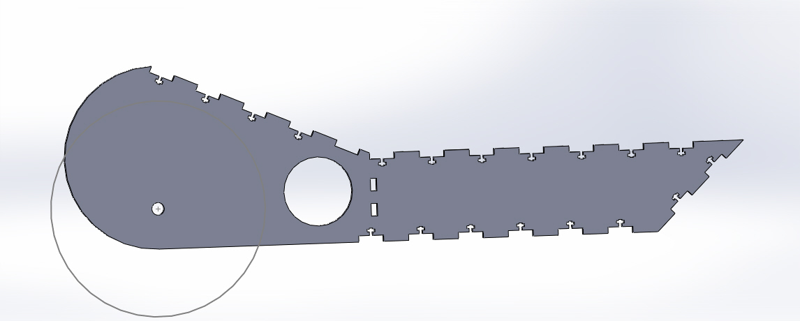
My design revolves around the use of a waterjet to make the majority of the frame but relies on bolts and nuts to hold the entire thing together. The way I accomplished this was using a very popular interleaving system and adding T nuts to every other interleave. This allows the stress to be distributed to multiple small bolts, (6-32), without coming apart or sheering the small bolts. But because of the costs associated with waterjetting it was important to be extremely confident on the scooters frame before having all the parts fabricated. This was achieved by using standard cardboard and a laser cutter. Though the mock-scooter frame would in no way be structural, it did allow me to be able to gauge the size of various components as well as the fit for the motor and battery compartments. Once I had determined everything was correctly sized and placed, I put in my order in with BigBlueSaw.com .
Fabrication
Though MIT has many waterjet's on campus, when I first started working here I did not have direct access to any of them. In theory I could have convinced a friend to waterjet the parts for me, the costs of waterjet time ($3/min) + plate stock ($$$) for all the parts, it seemed more prudent to work with a company to have the parts made to reduce my costs as well as insure the parts came out pristine.
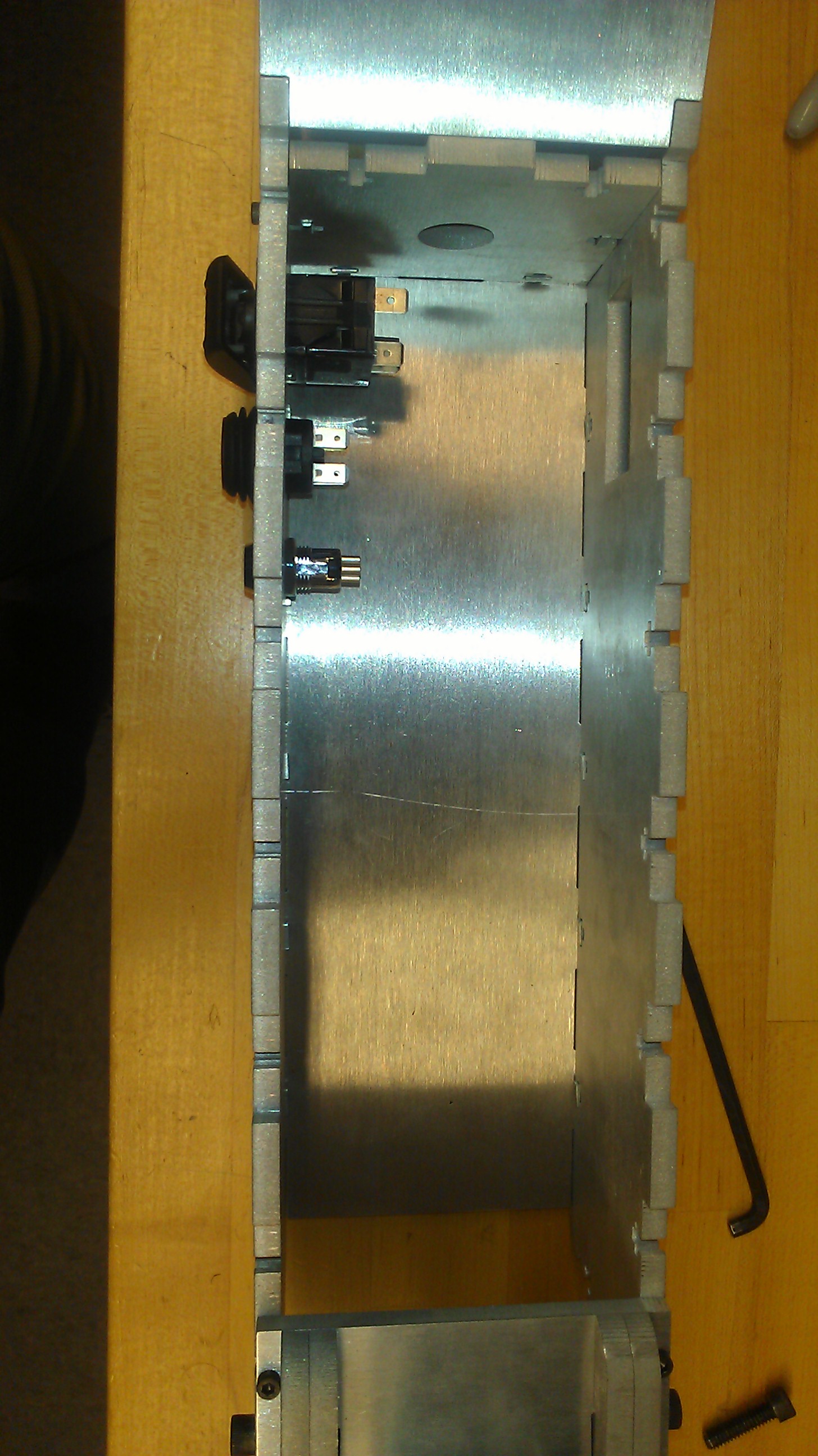
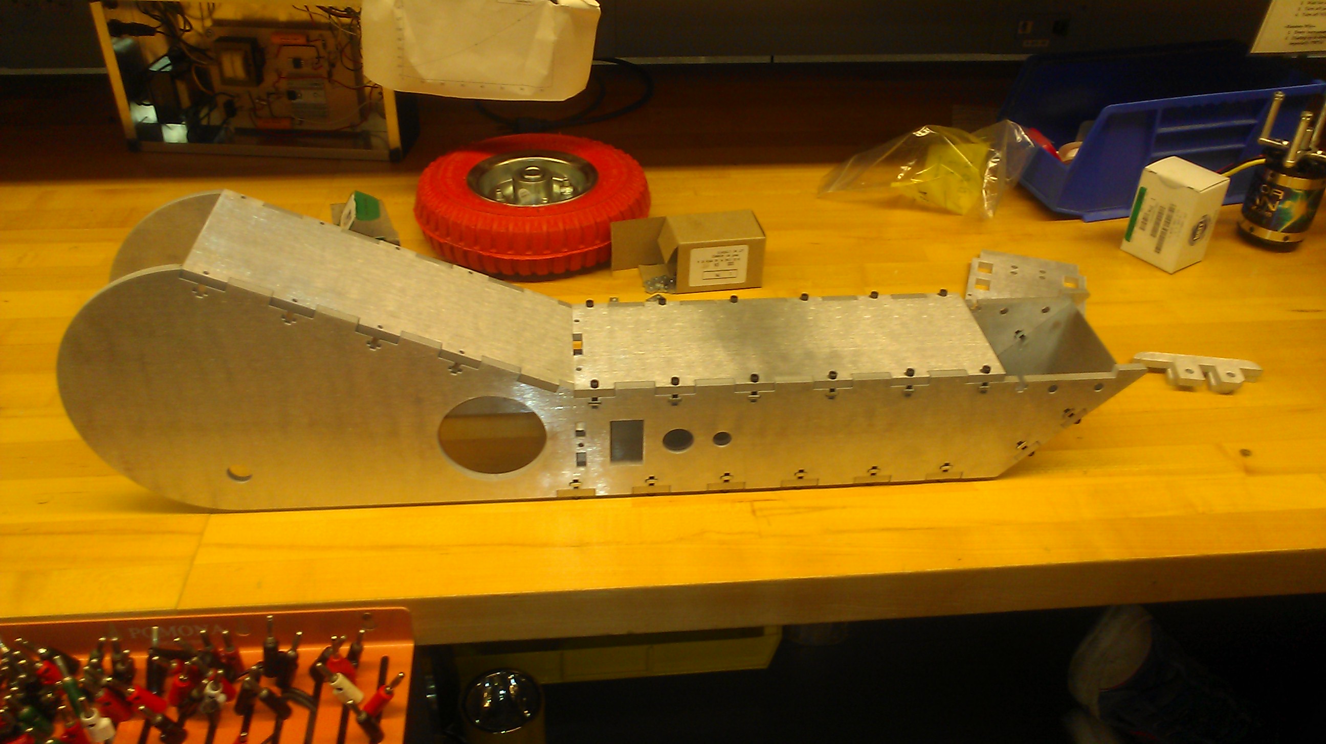
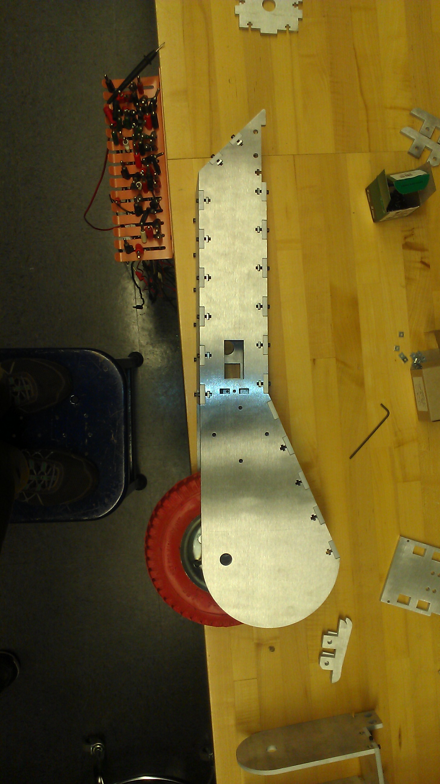
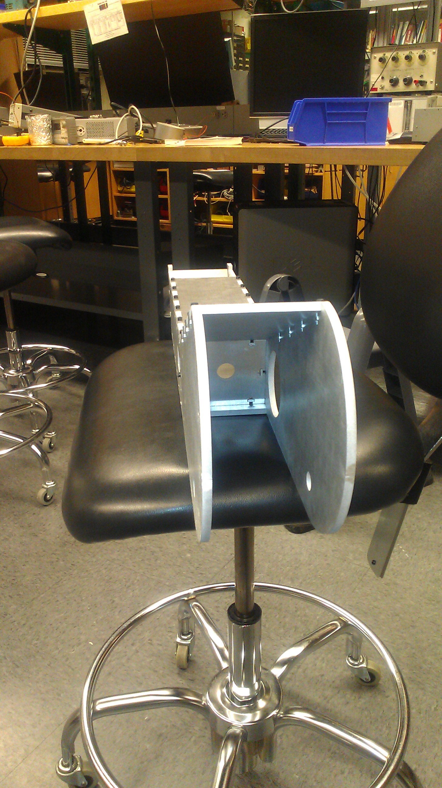
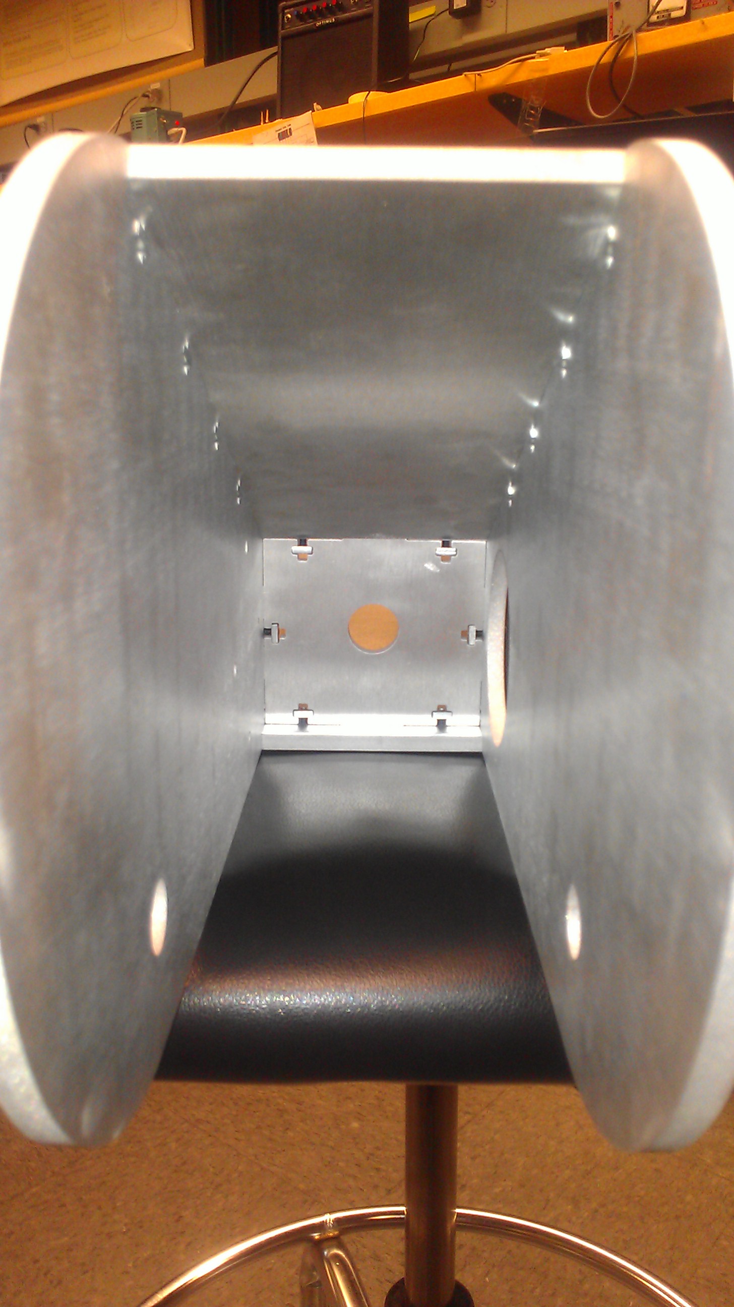
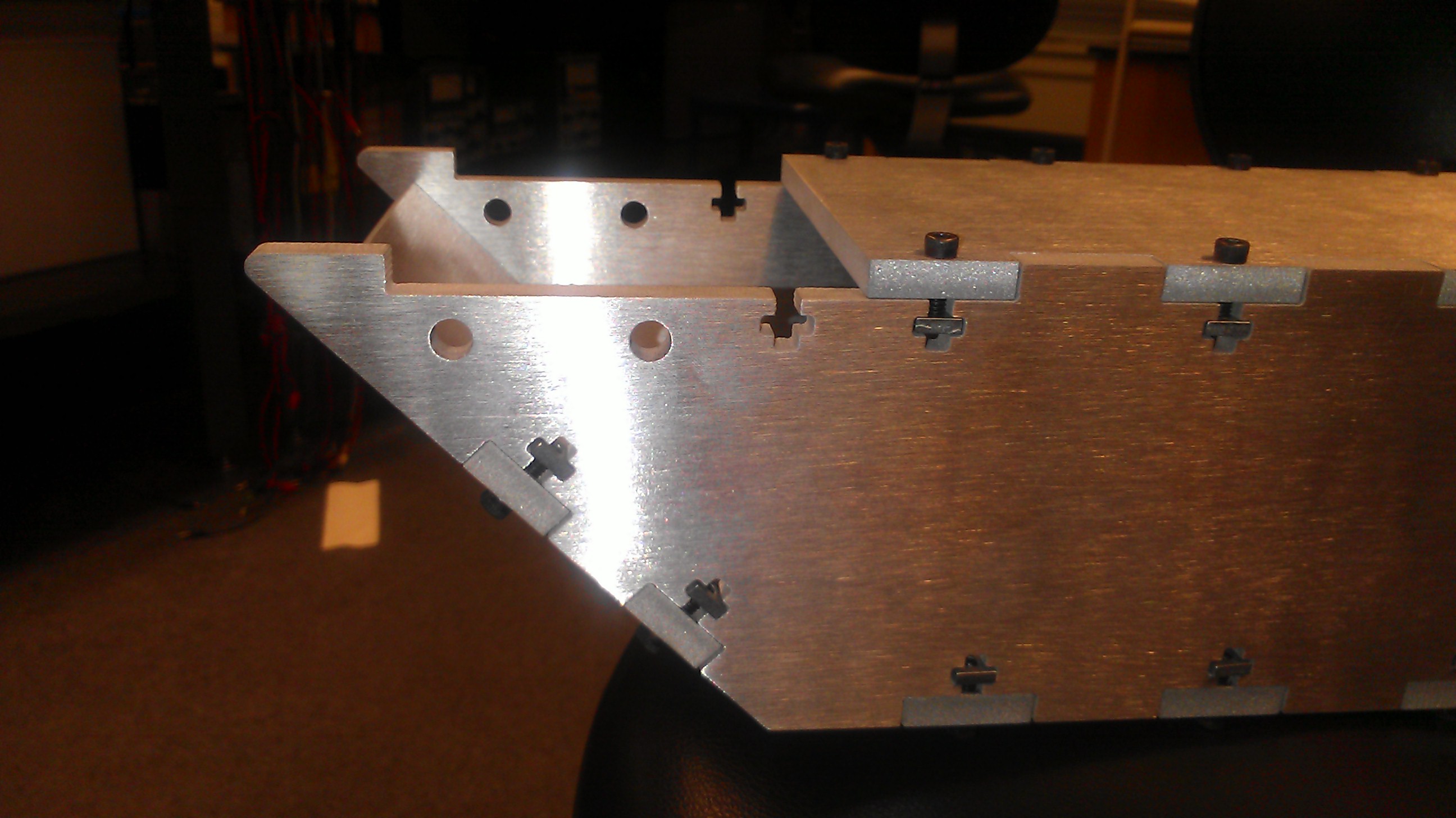
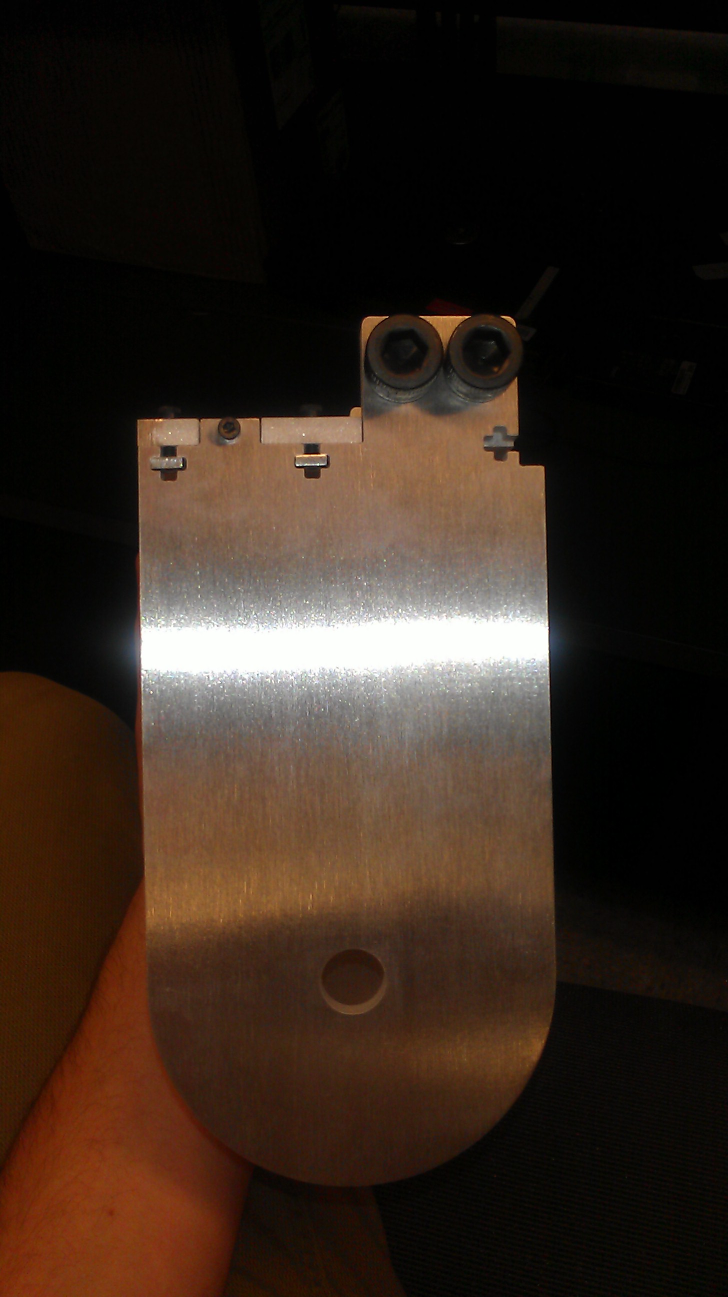
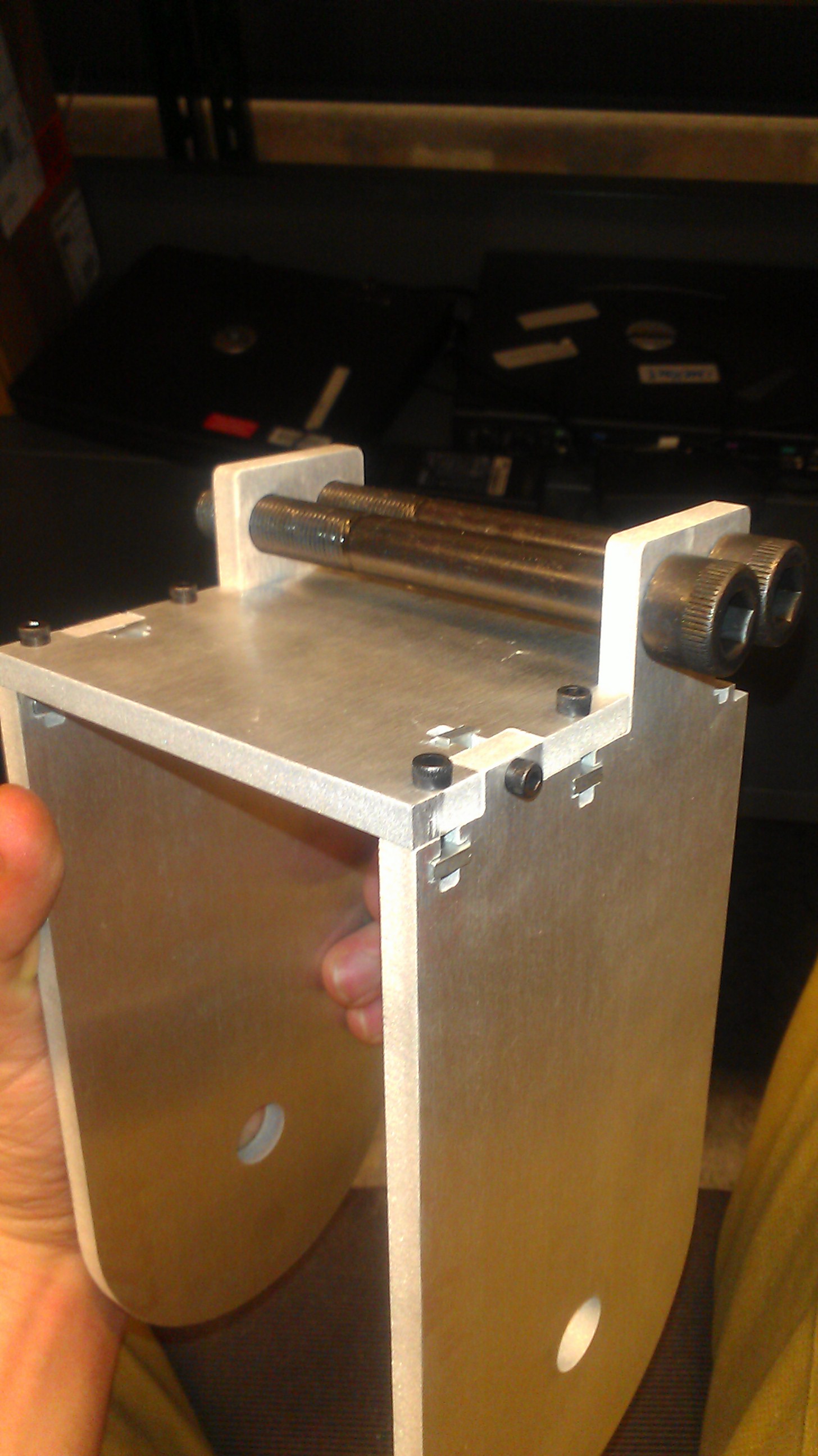
Once the parts arrived, I immediately assembled the frame. Overall the frame fit together quite well with the expected slight modification or two of a few components that could not be manufactured by 2d cutting alone. The most important section of my frame was the mounting system between the handle bars and the frame itself. From research into the failure modes of other electric scooters around MITERS, I have found that most people do not strengthen the mating surface connection at this point. This ultimately leads to the cracking and bending of the aluminum around this stress point. To combat this, I designed a relief system that used sturdier bolts which were mounted horizontally through the side plates and went through two T pieces on each side of the mounting plate. This design allows for the bending stress to be directly transferred from the plate, through the T's to two 1/4"-20 bolts on each side. Since a majority of the bolt is surrounded by plate (side plate or T's) there is little room for the bolts to ever bend, and not enough force for them to sheer.
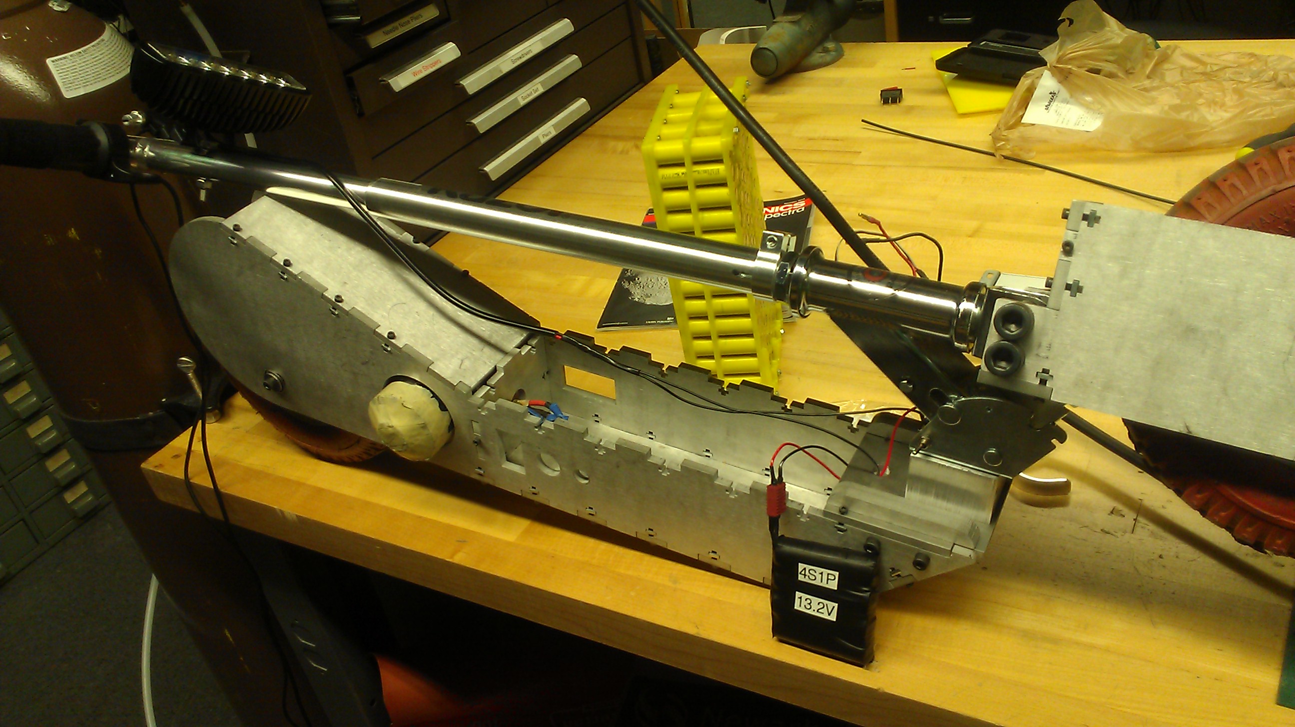
The next step was modifying my razor scooter handle bar assembly to mount straight to the frame. This was done through a simple 2 in thick block of aluminium. The top of the block has mounting holes for bolts that originally bolted the fork to the original scooter frame, and the bottom has 4 tapped holes.
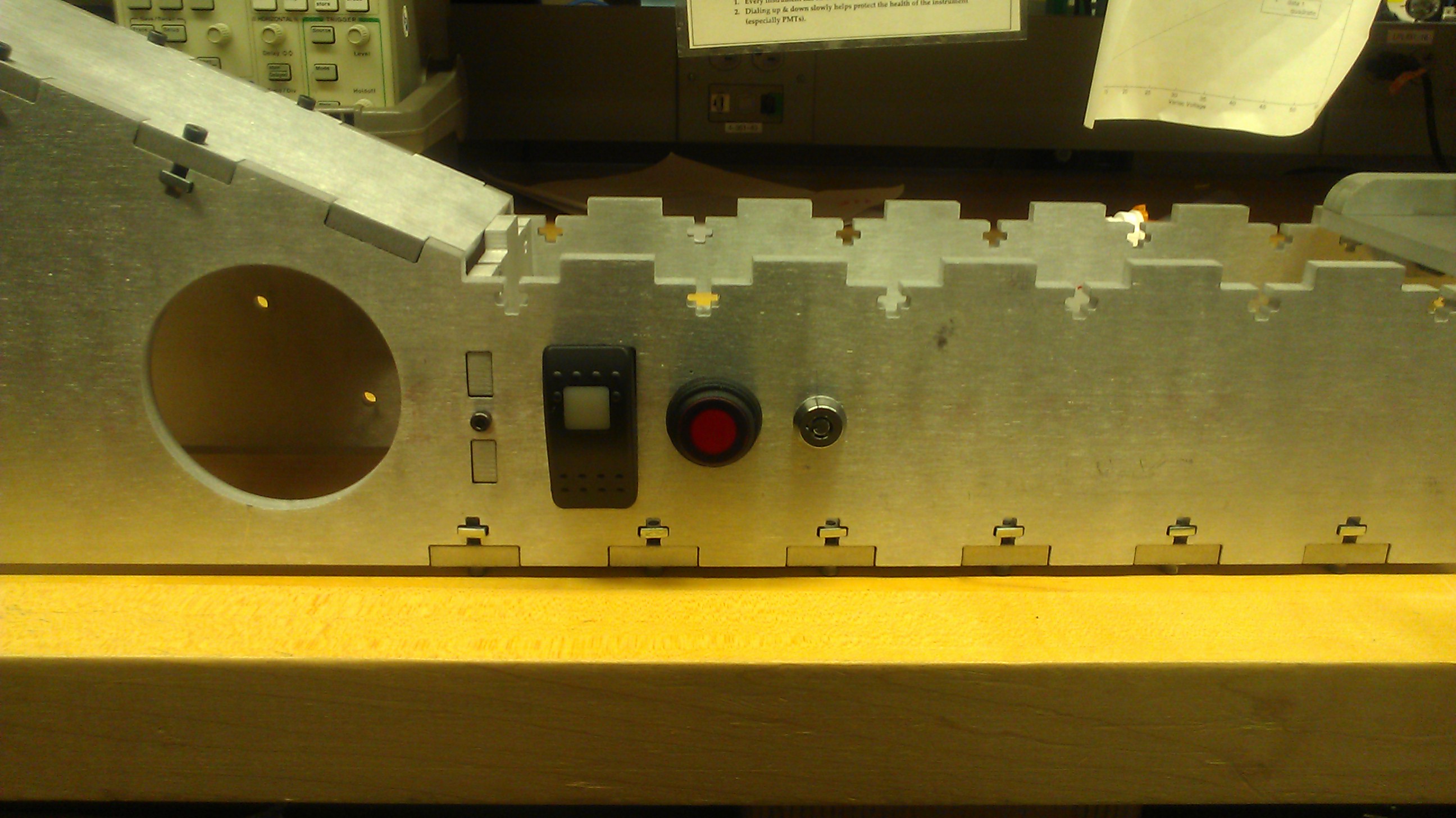
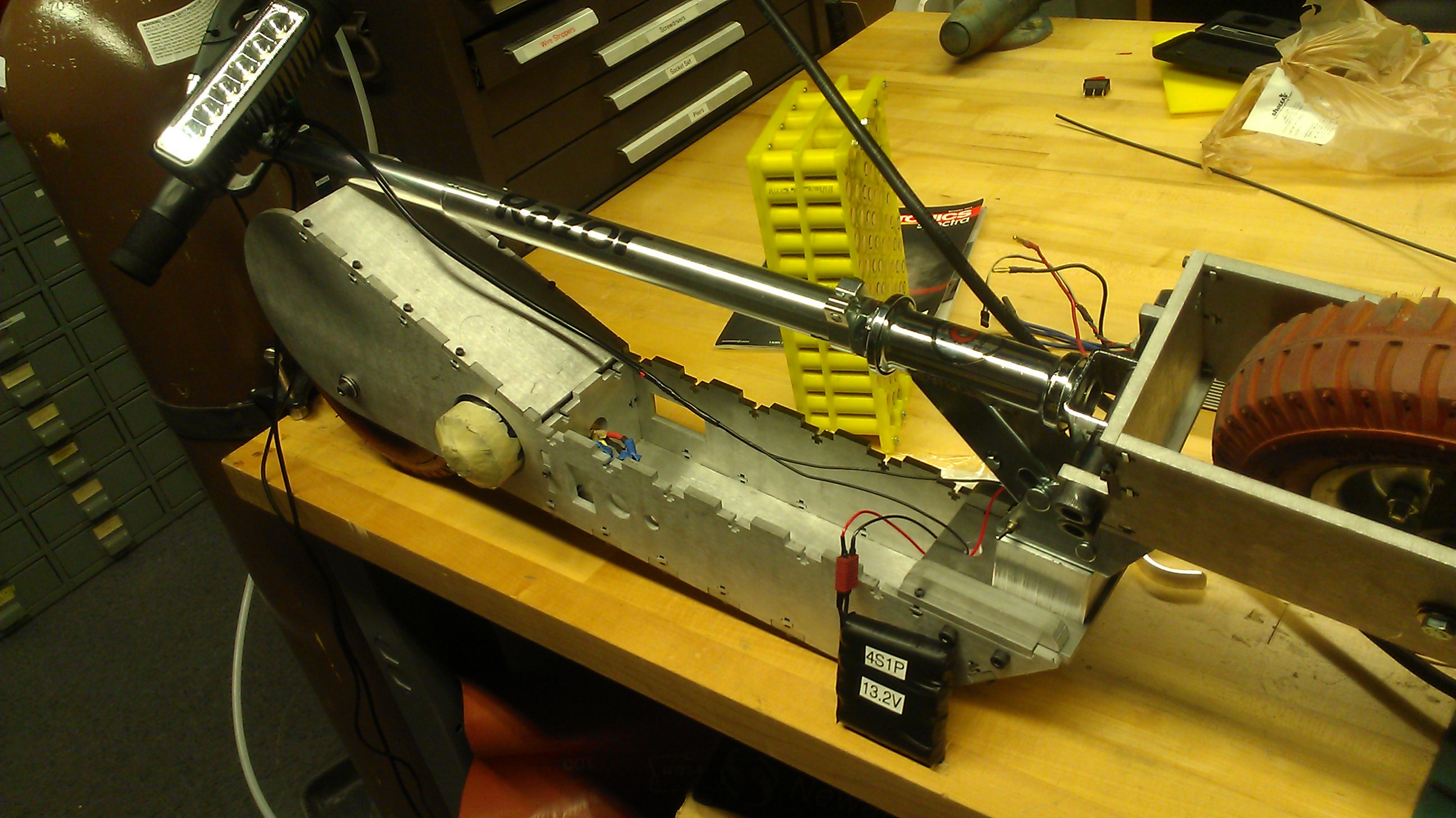
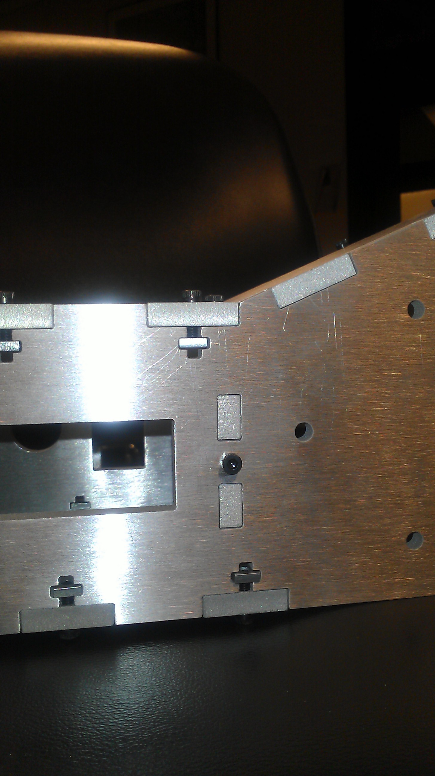
The two main errors overlooked in the design process were: (1) interference of back side of switches with the protective sodabottle armor on the batteries, (2) lack of chain tensioning.
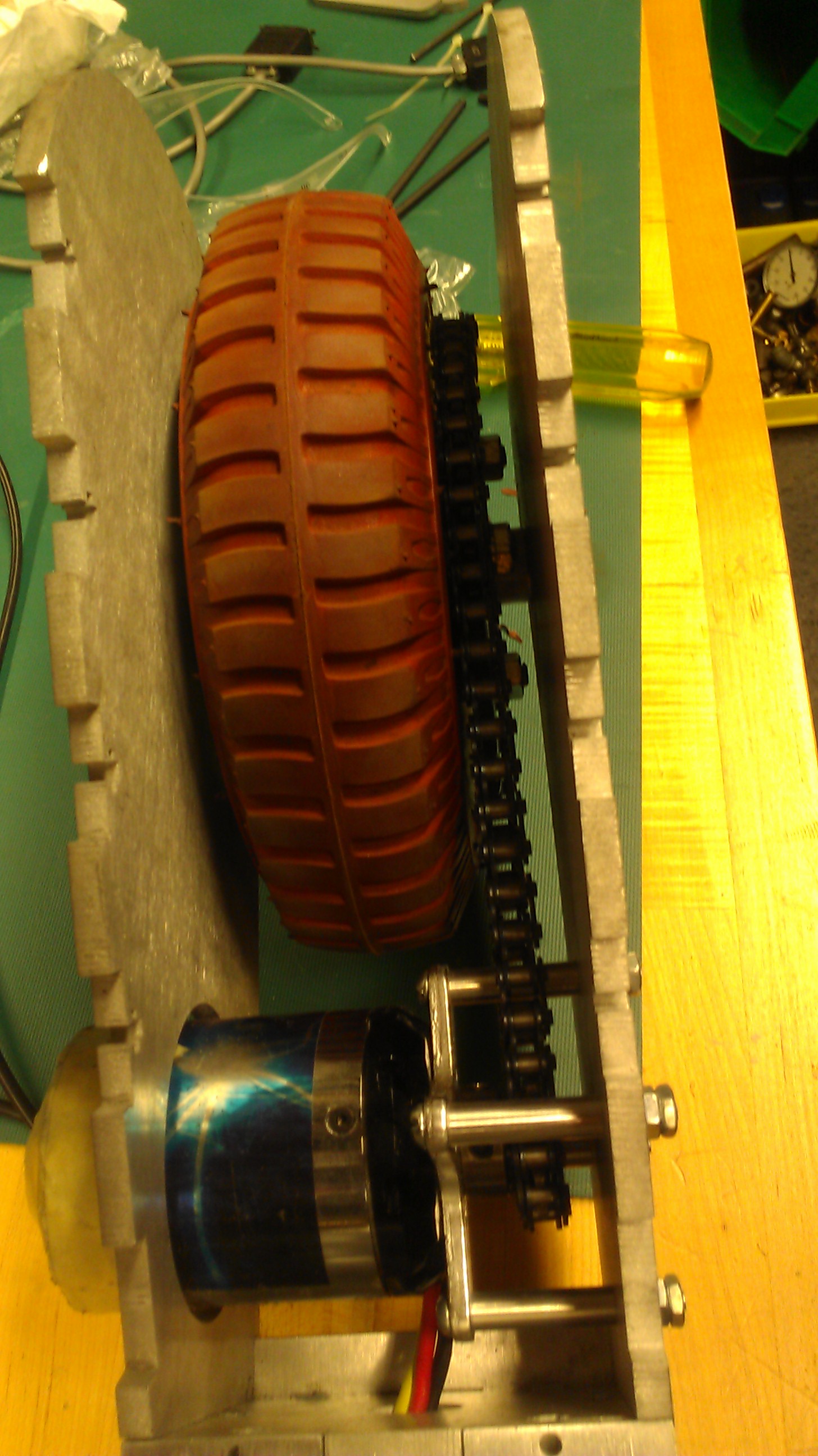
To solve the second problem, I used a standard tensioner from a moped. To adapt this to an already constructed frame, I milled out a L slot on both side plates. I also drilled and tapped two holes on each side plate for the tensioner to catch on. The idea of this tensioner is that you mount it to your wheel axle and use threaded nuts to pull the wheel axle back, and thereby tightening the chain. It has worked moderately well for an after the fact addition.
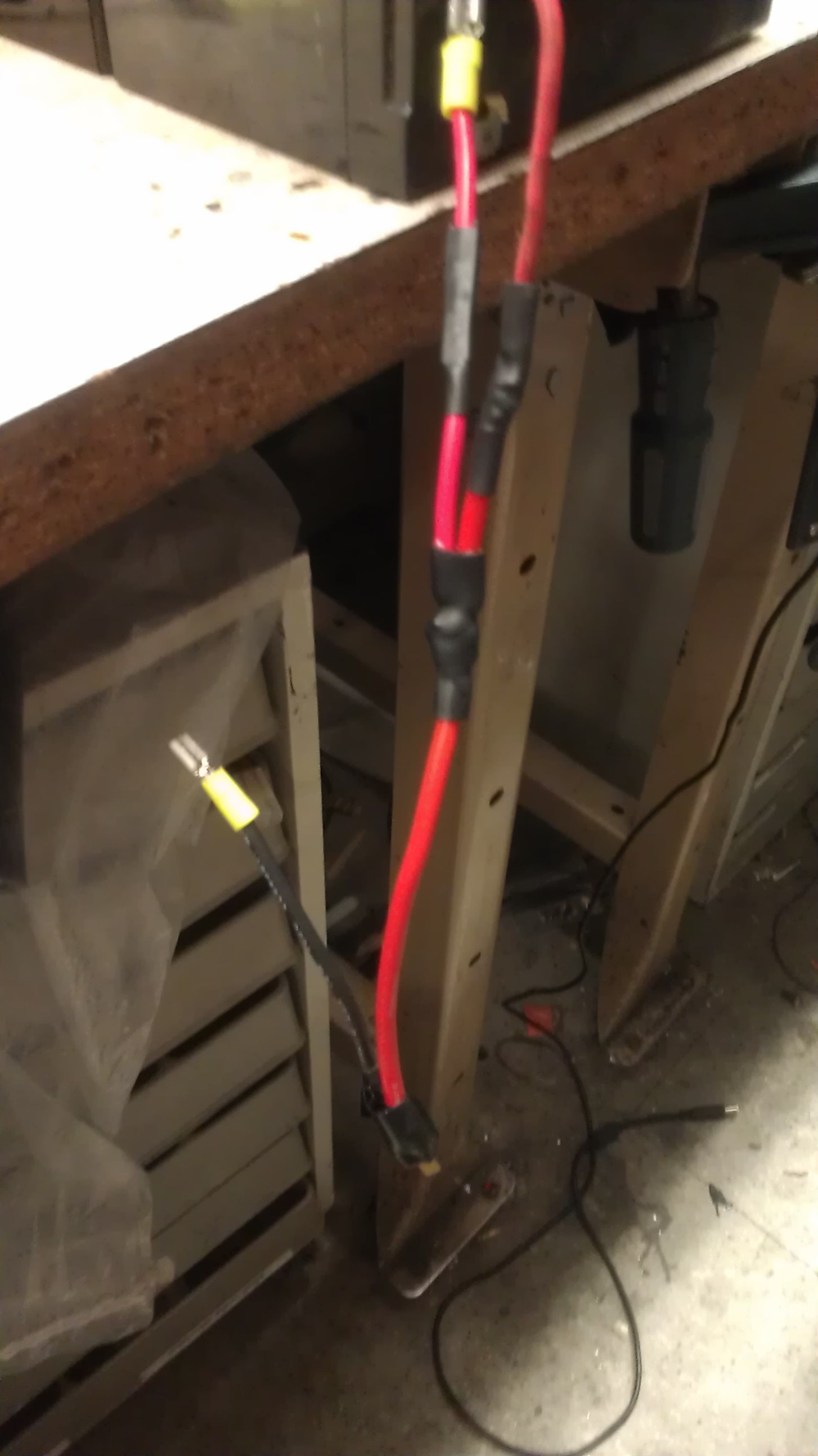
To solve the switch problem, I ended up having to drop my pre-charge and key switches to allow for enough clearance room for the battery and its external armor.
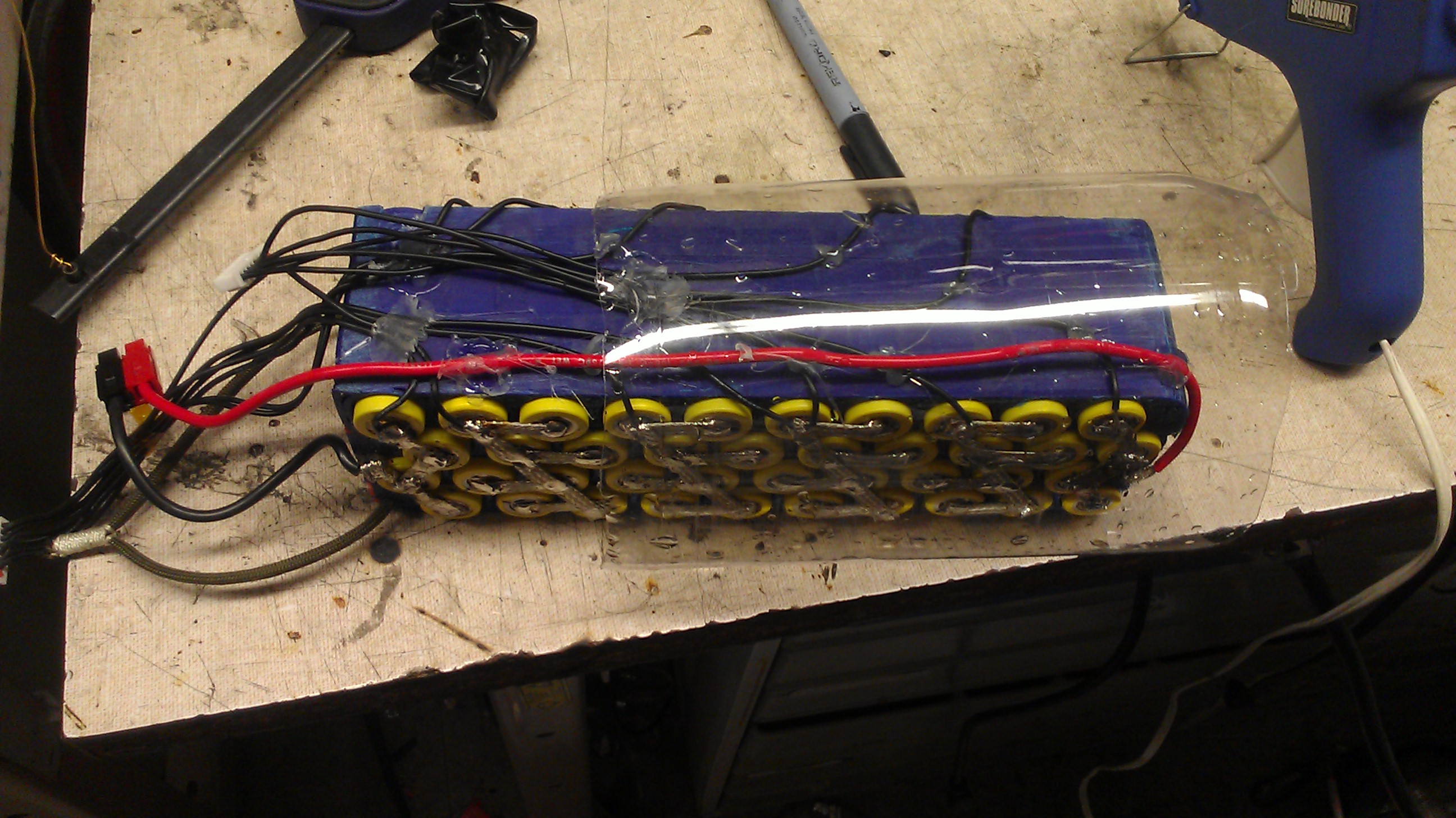
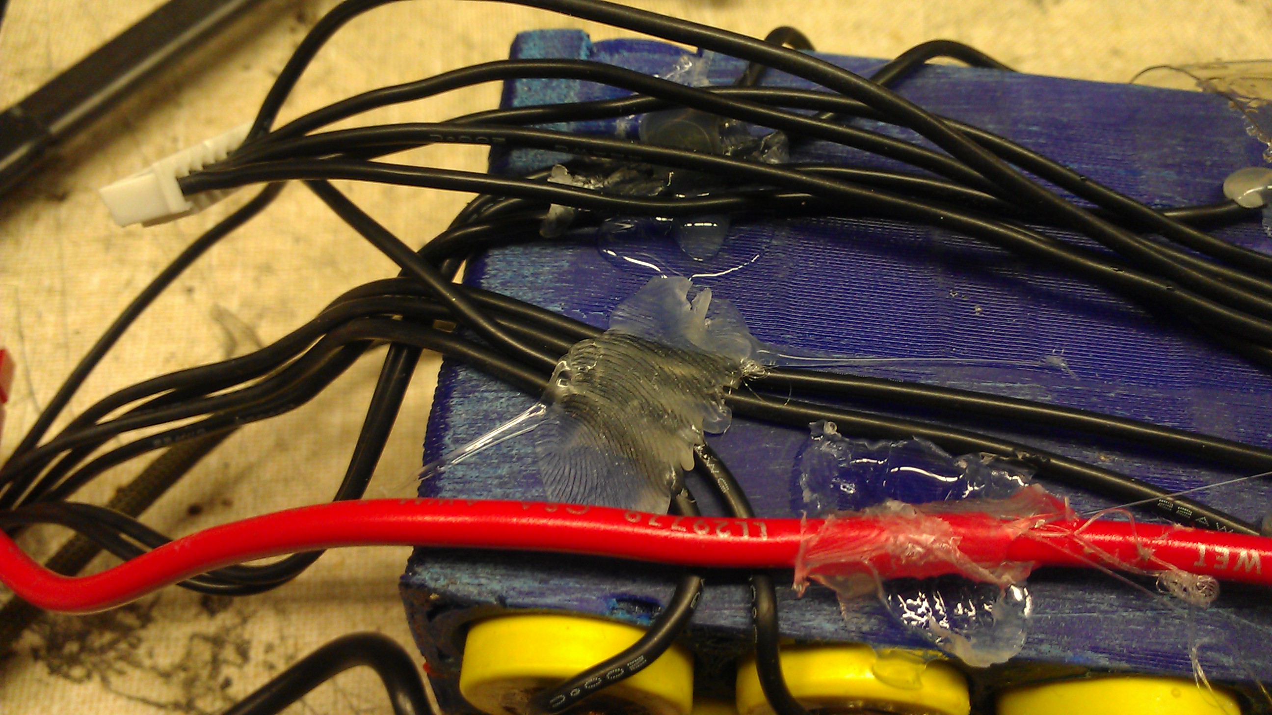
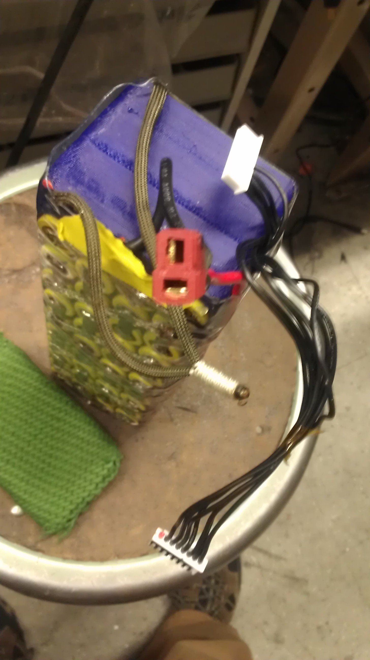
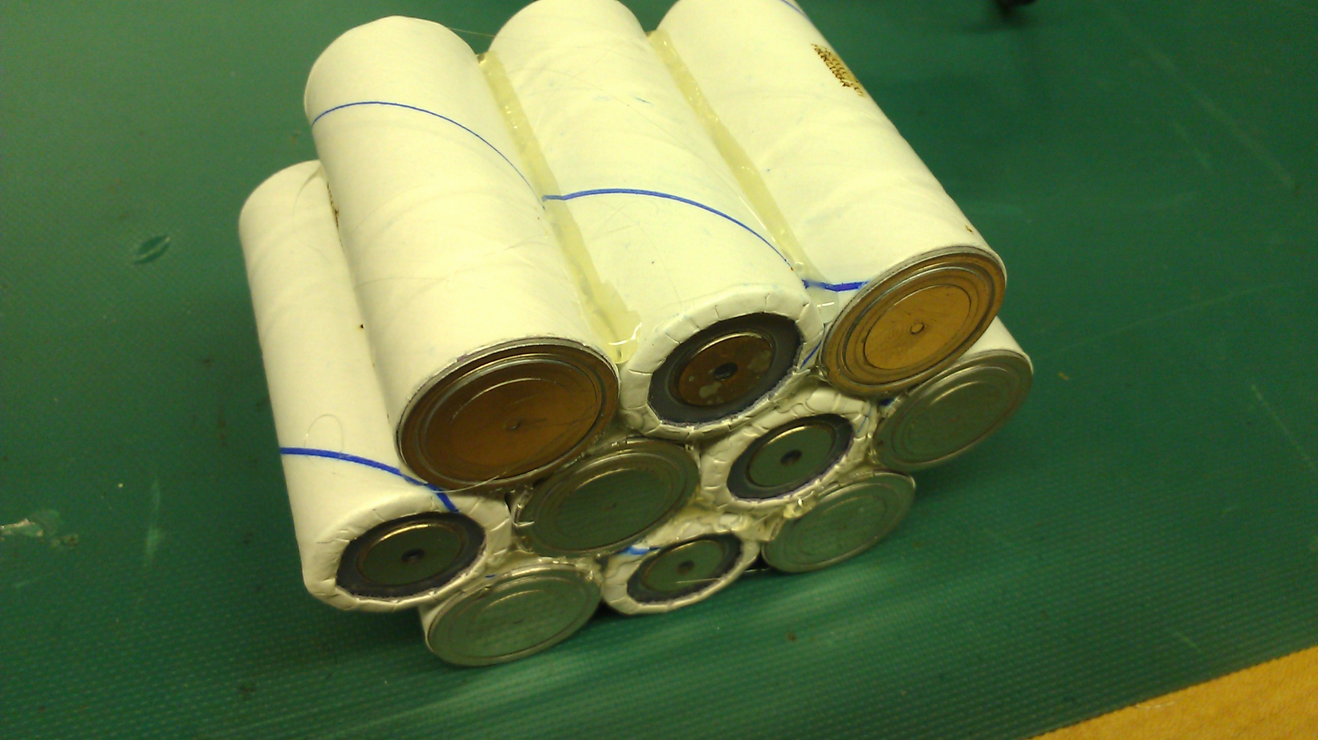
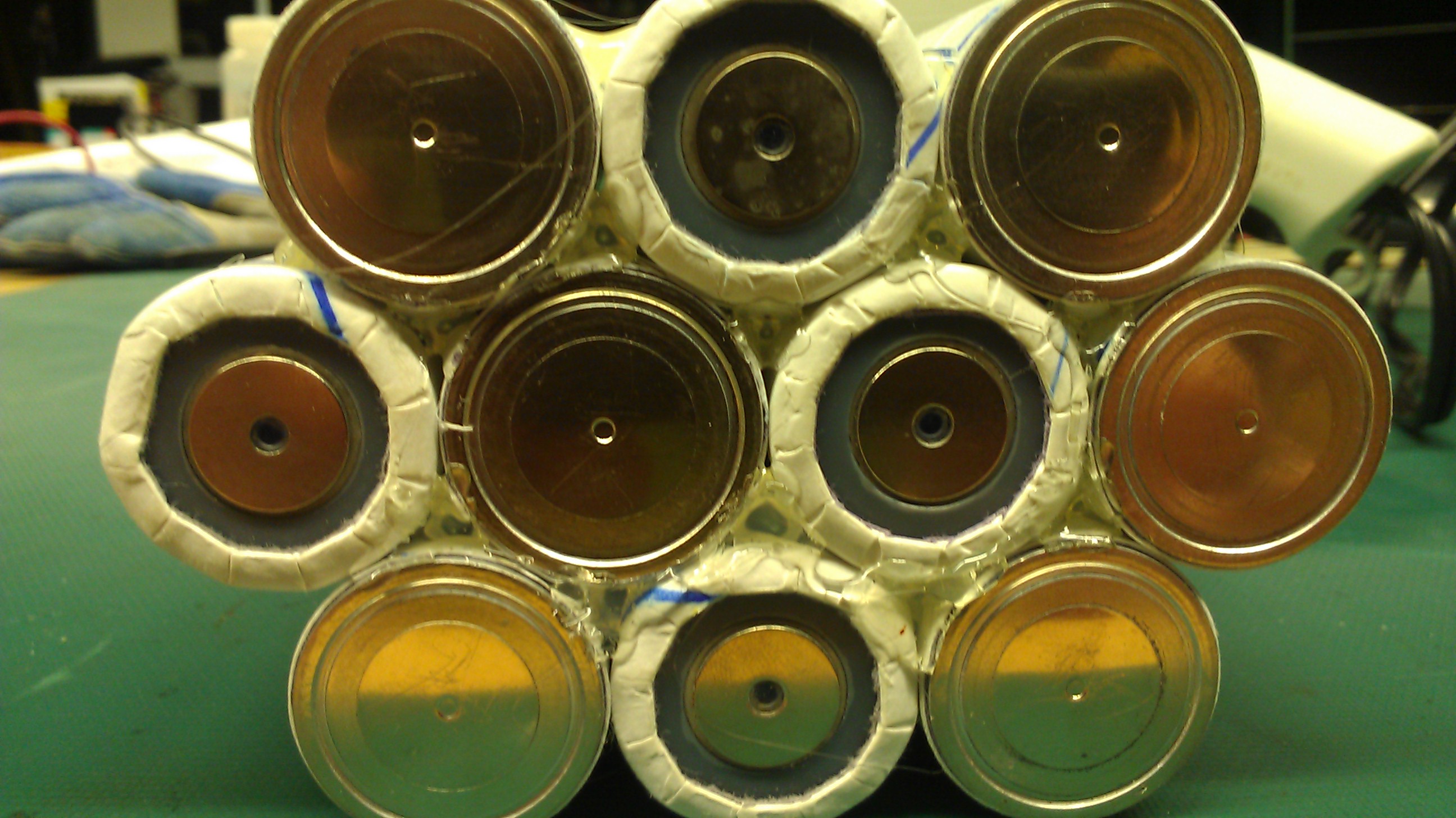
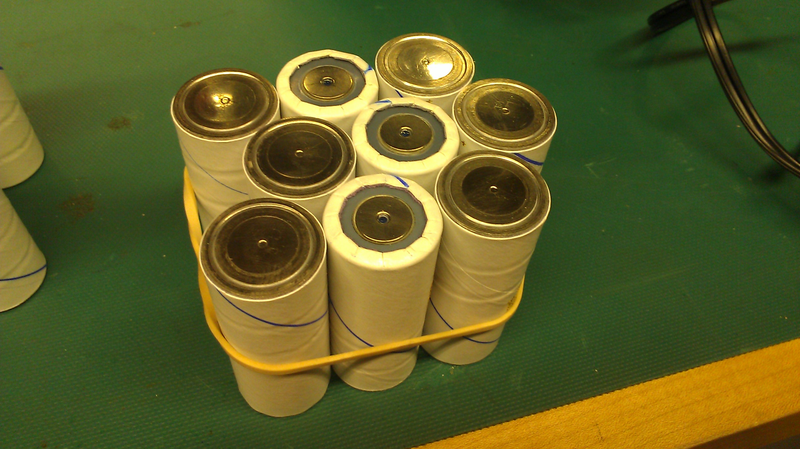
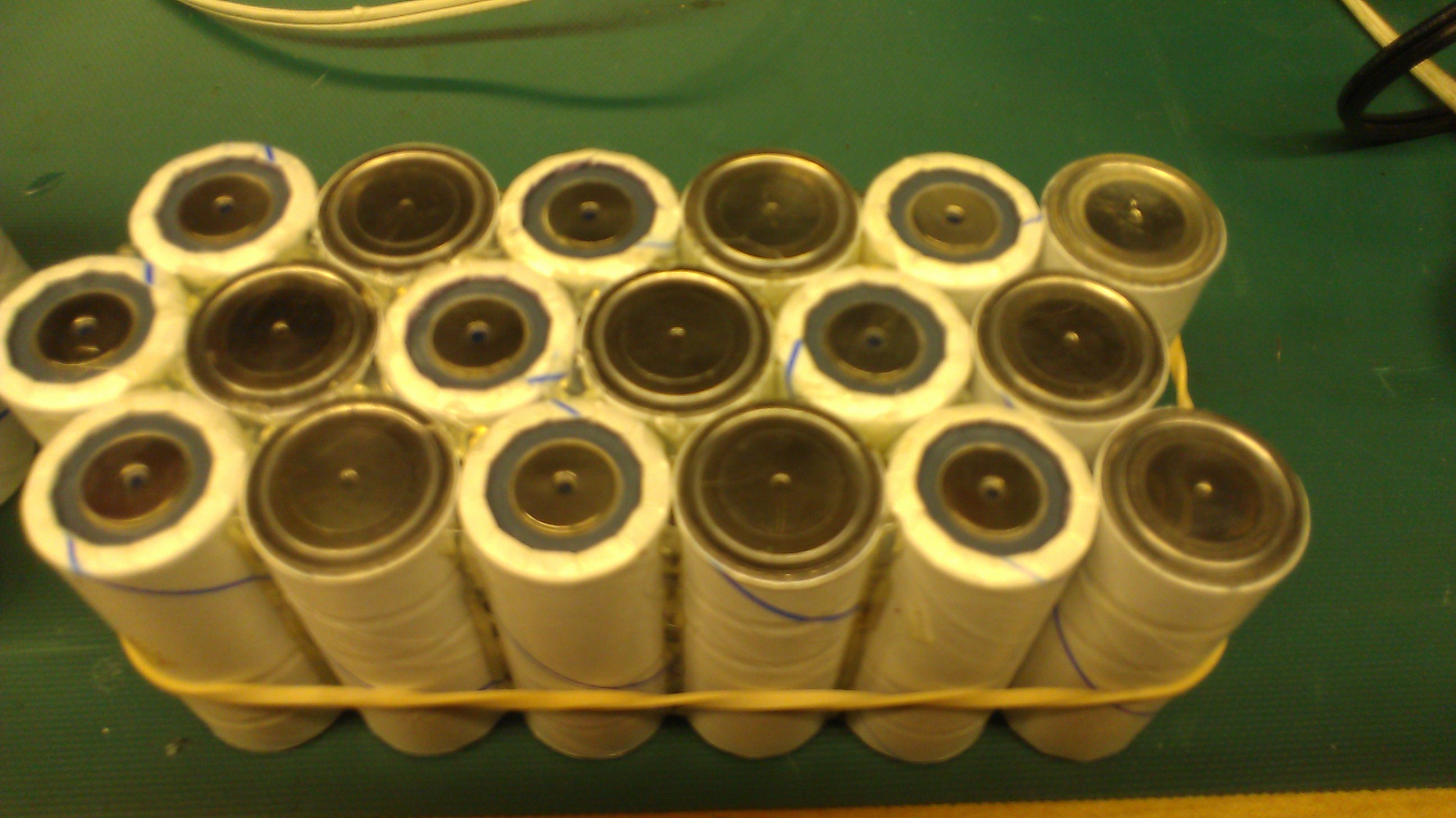
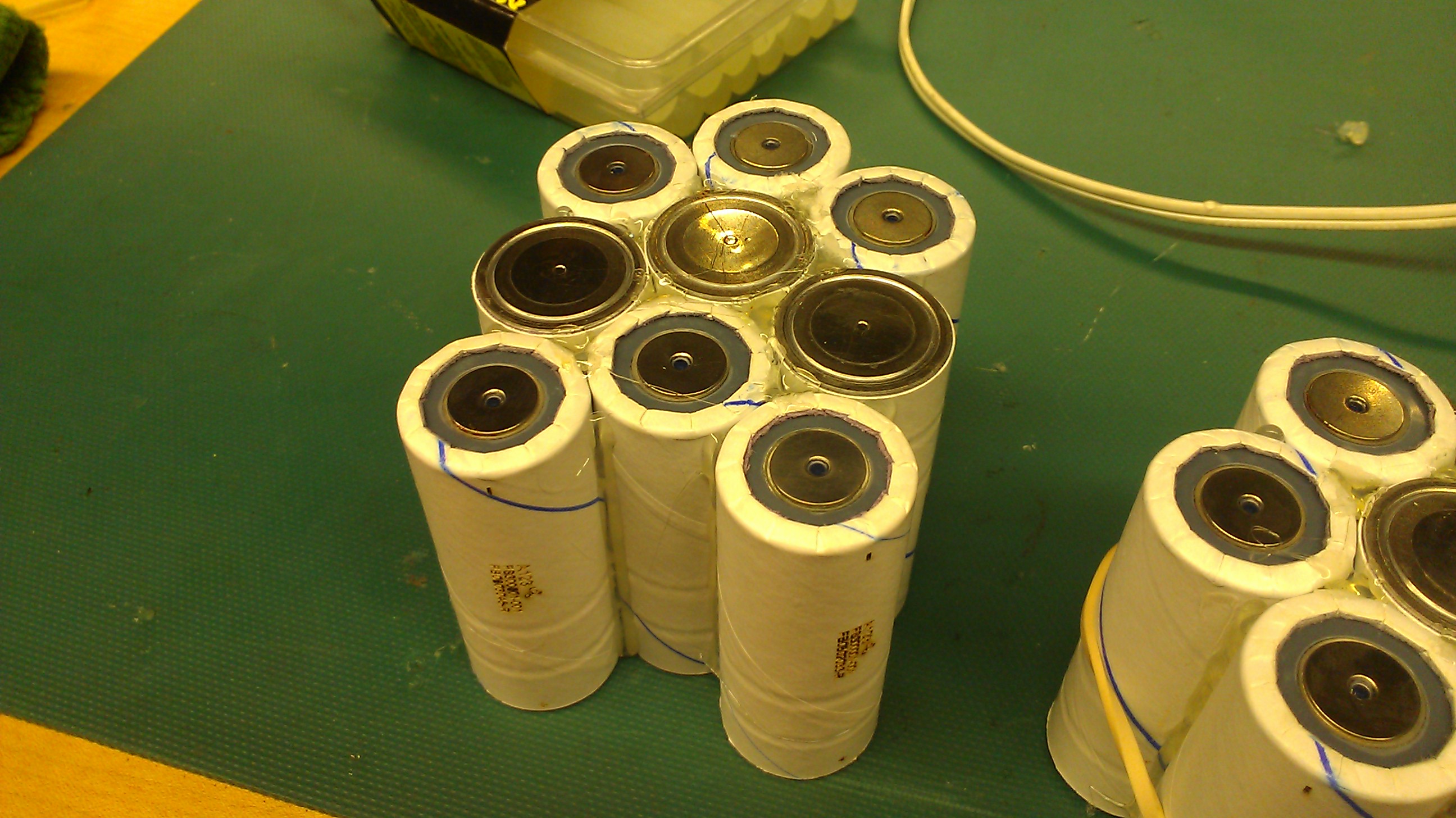
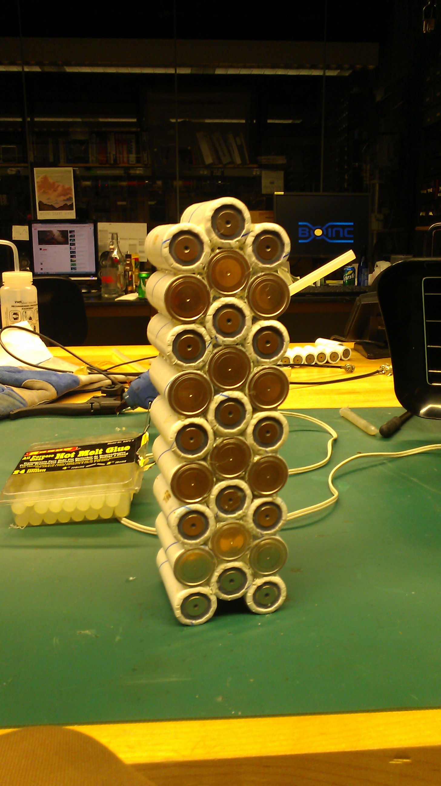
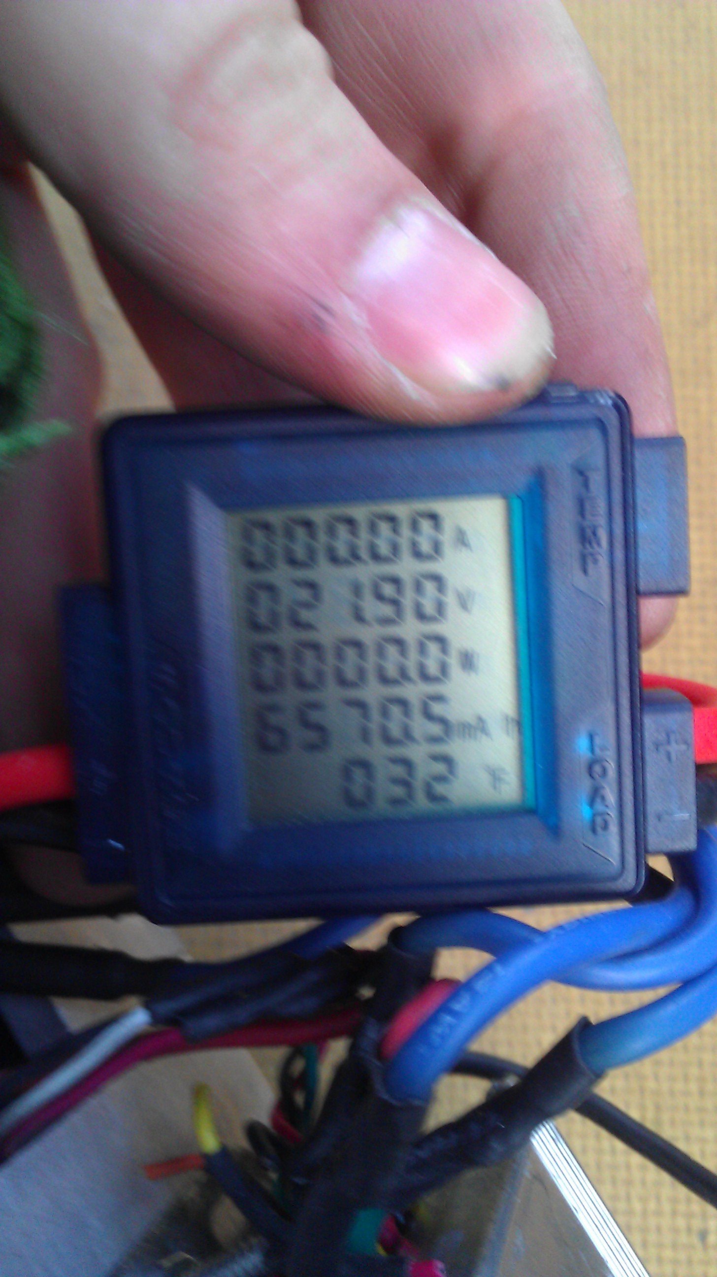
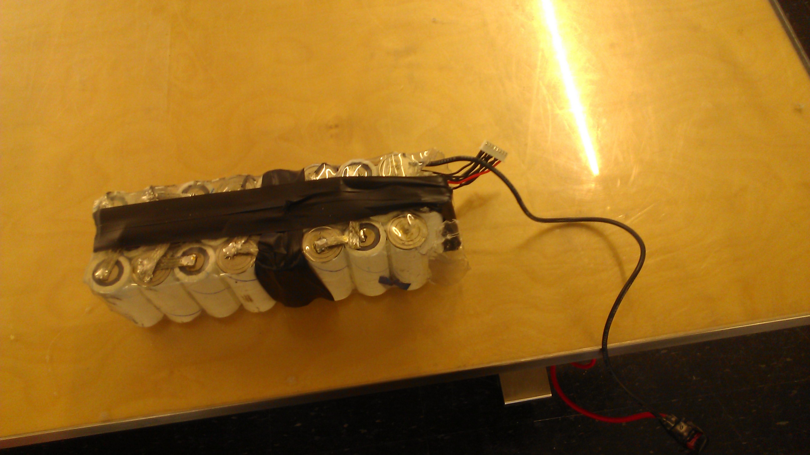
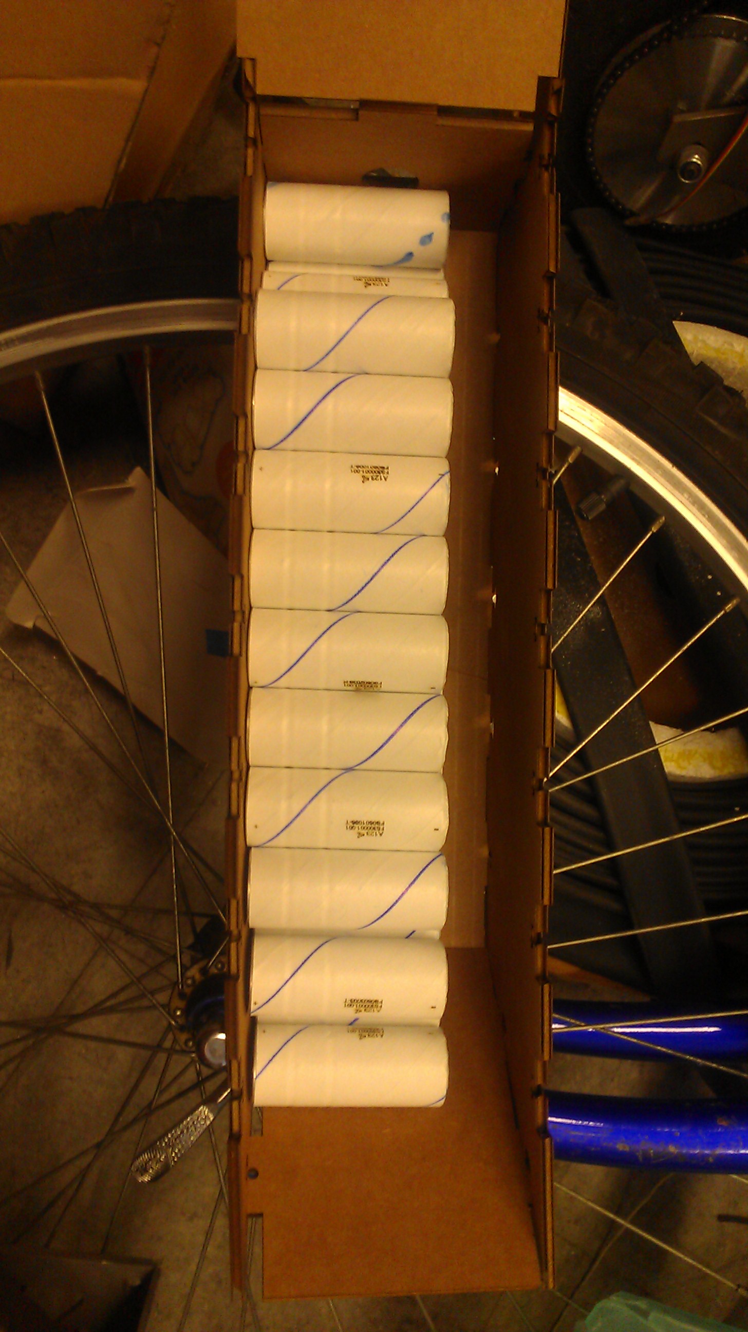
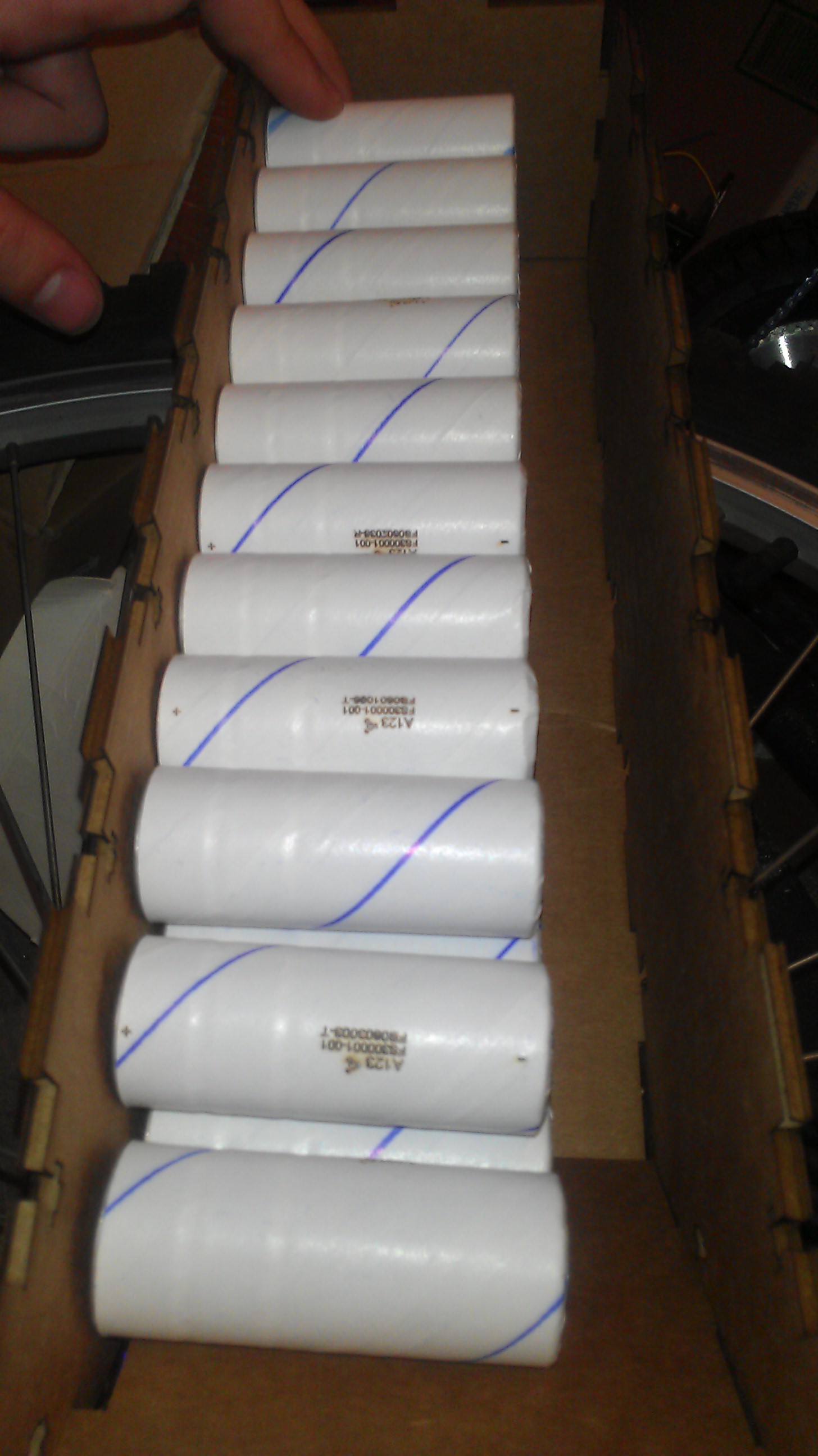
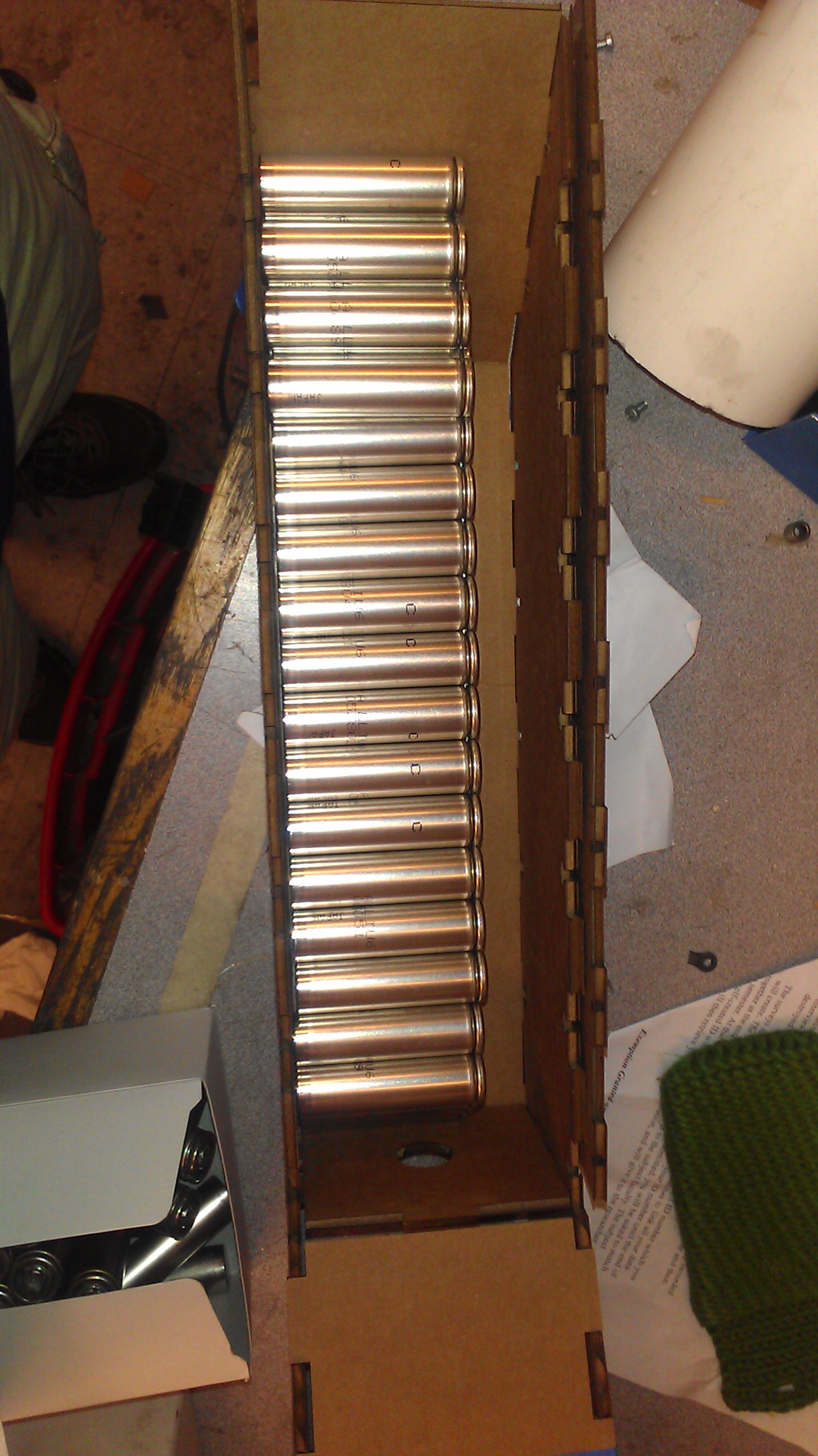
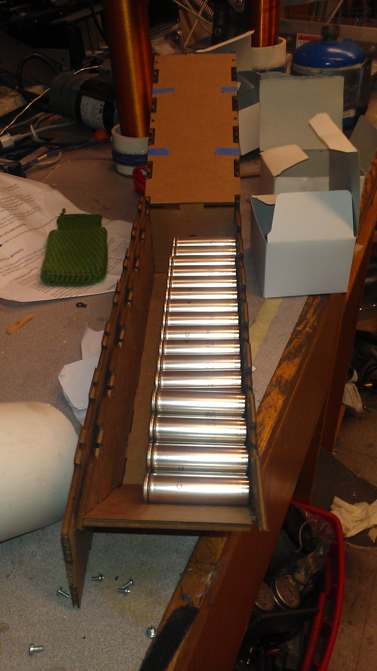
The battery is an array built of 26650 A123 lithium cells which were donated to MIT. The battery is arranged as a 9S3P (9 Cells in series, 3 sets in parallel.). My first pack used a 3D printed battery holder box for aligning the cells and protecting them from being crushed. It also featured a 2L clear soda bottle armor, this is done by taking 2 Liter bottles of soda and heating them which causes them to shrink tightly around your battery. (I.E. - Heavy Duty Shrink wrap). This first battery suffered an unfortunate mishap when a Coulomb counter was left plugged into a lower battery overnight, ultimately bringing multiple cells to an extremely low voltage.The second battery was made without the fancy 3d printed box, and relied solely on hotglue to hold the cells together before being soldered in place. It is important to note that every battery I make comes with a standard balancing lead setup.
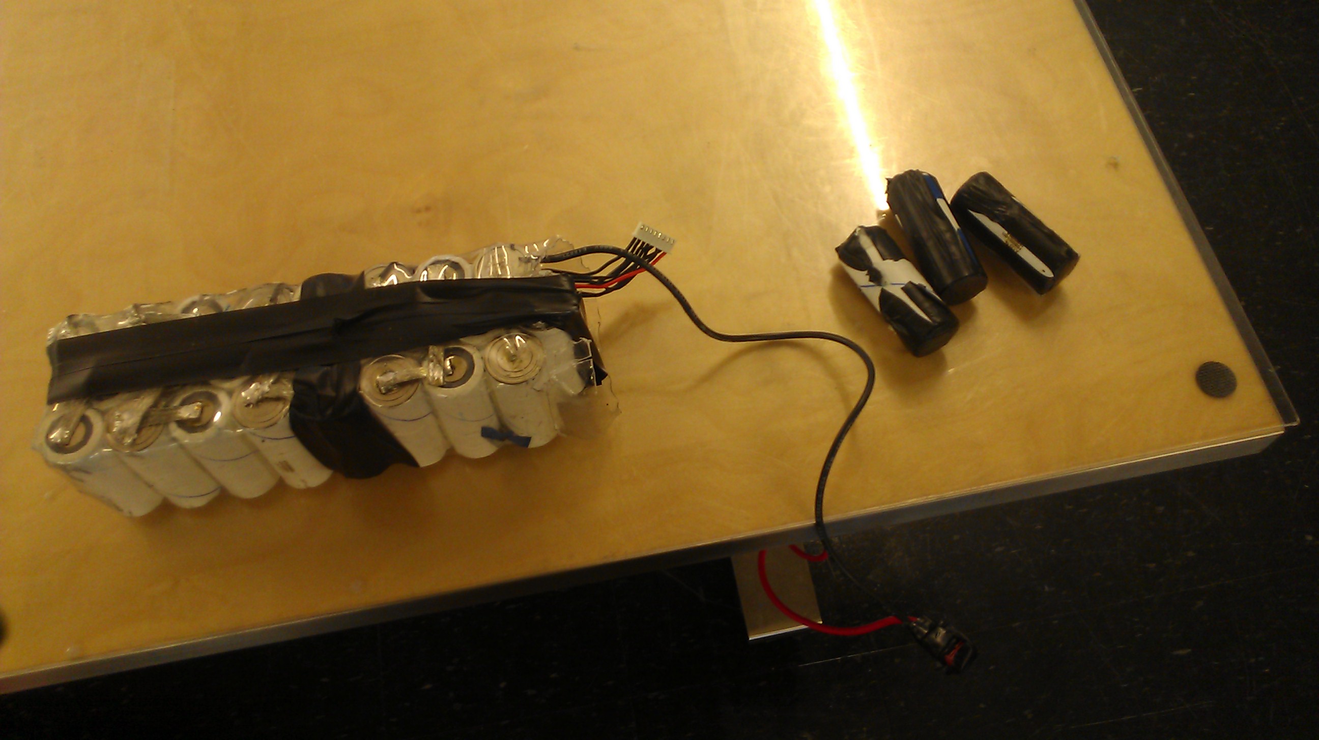
Sadly, this battery suffered the scariest issue you can face with a lithium battery... a short. After using the pack for a couple of trips, once of the contacts on the end either was soldered without enough heat or felt enough force to become undone. Some how the lead to one of the end cells to become shorted when I was man-handling the frame. Luckily I noticed the heat build up and rushed into act, ultimately removing the end 3 cells. This incident could have lead to a battery fire, but I was lucky that I have not become desensitized to the dangers of Lithium cells yet.
Ultimately, I built a third and final battery. This one being the one that has lasted for multiple years without fail. The whole battery ordeal was definitely a teaching moment, but the biggest take-away was that I really should figure-out how to get a BMS installed onto my larger vehicles for battery monitoring and cut-offs to reduce damage to cells.
Overall this was a long, but rewarding projects where I learned a lot about batteries. I definitely would suggest everyone to try their hand at a small electric vehicle some time (I prefer sensorless, but that might be because I don't like the failure mode when my sensor ends up getting knocked off).