[1.14.2012]Handicap Button: Dis-assembly of a used Wireless Handicap Button

Description of Project
The Disassembly of a Used Wireless Handicap button to determine and understand how it works.
Processes Applied:


disassembly
Summary:
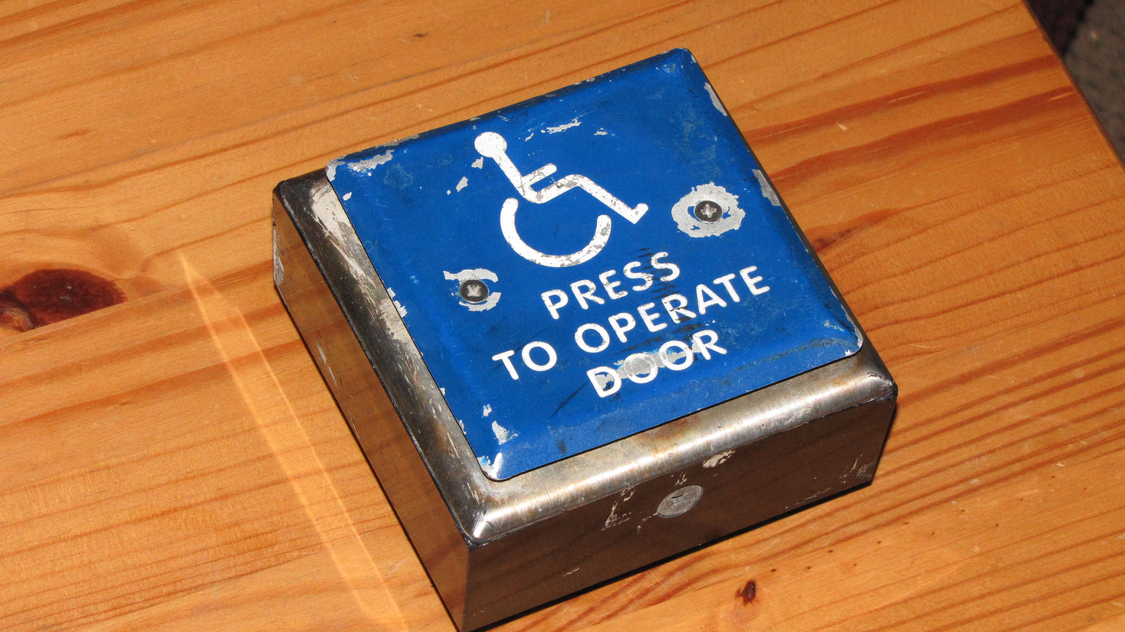
This project was the disassembly of a Used Wireless handicap button which I acquired out of the RPI Techdumps. The condition of the outer casing was quite worn, rusted, and used. The reason that they junked it in my opinion is that the screws were rusted and stripped making it impossible to open up the case without damaging the button. The reason this makes the button useless is that there were 4 wall screws located in the back of the case, the only way to screw them into a wall requires that the case to be opened.
Removing the lid of the case was tedious and required an application of force and leverage. I was able to remove 1 screw of the two screws holding the lid on the box by a variety of methods, the initial was using tin foil in the groove of the screw to allow the screwdriver to function properly in the face of a stripped screw. I had only partial success with this method and ended up using force to get the screw past the initial stuck position. After I was able to do this, I used a pair of pliers and removed the screw by a combination of both screwing and pulling. Once the first screw was out, I started on the second; using all the same methods to no avail. Once I determined that the second screw was permanently embedded in the hole, I pried the lid up and was able to see how the lid was held into place using angled iron and a larger screw on each side of the box; sadly, they were also stuck in place. Ultimately, I ended using force and leverage to bend and maneuver the lid around to allow for access to the internal guts of the handicap button after I disconnected the button mounted underneath the handicap button panel.
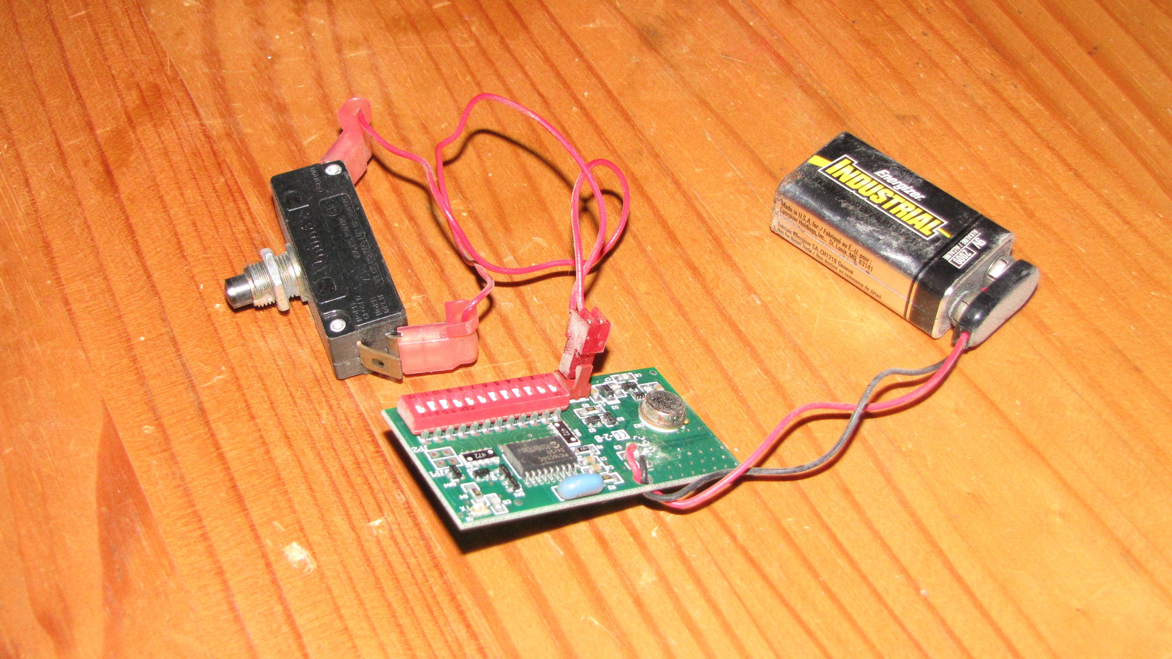
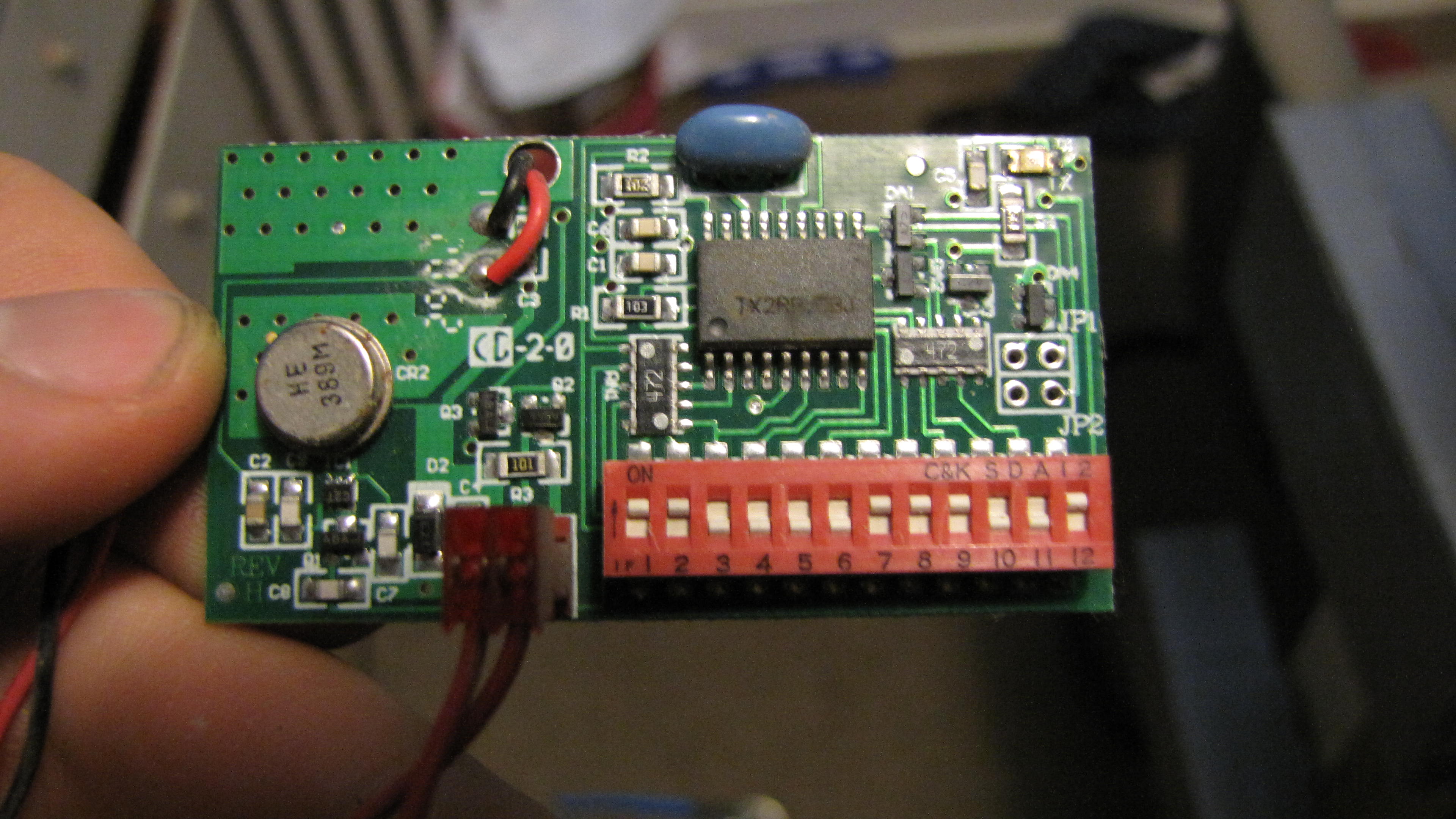
The internal circuit was simple and was mounted on a small board compared to the size of the case. It ended up being mounted on the internal wall of the case and wired to a small push button, which was in turn mounted in a position under a circular ring that pushed into the button, which itself was mounted to the blue steel button we all know. The circuit comprised a 9-volt battery for power, a push button, and the circuit (Seen Below). The circuit comprised multiple capacitors, a broadband amplifier, capacitors, integrated circuits, and a panel of switches used as input for the integrated circuit. I tried searching for data sheets on the integrated circuits but the labels(names) were incomplete so I was unable to. From what I see, the circuit is set up to send a signal when the button is pressed and the signal is slightly altered depending on the positioning of the switches. Also when looking at the switches we can see that we can disable the button by putting switch 1 in the off position. The final note is that there is an indication LED in the top right corner that enables for 1 second after a successful signal has been sent.