[Jan '12]Chaos Pendulum: Double Pendulum
Description of Project
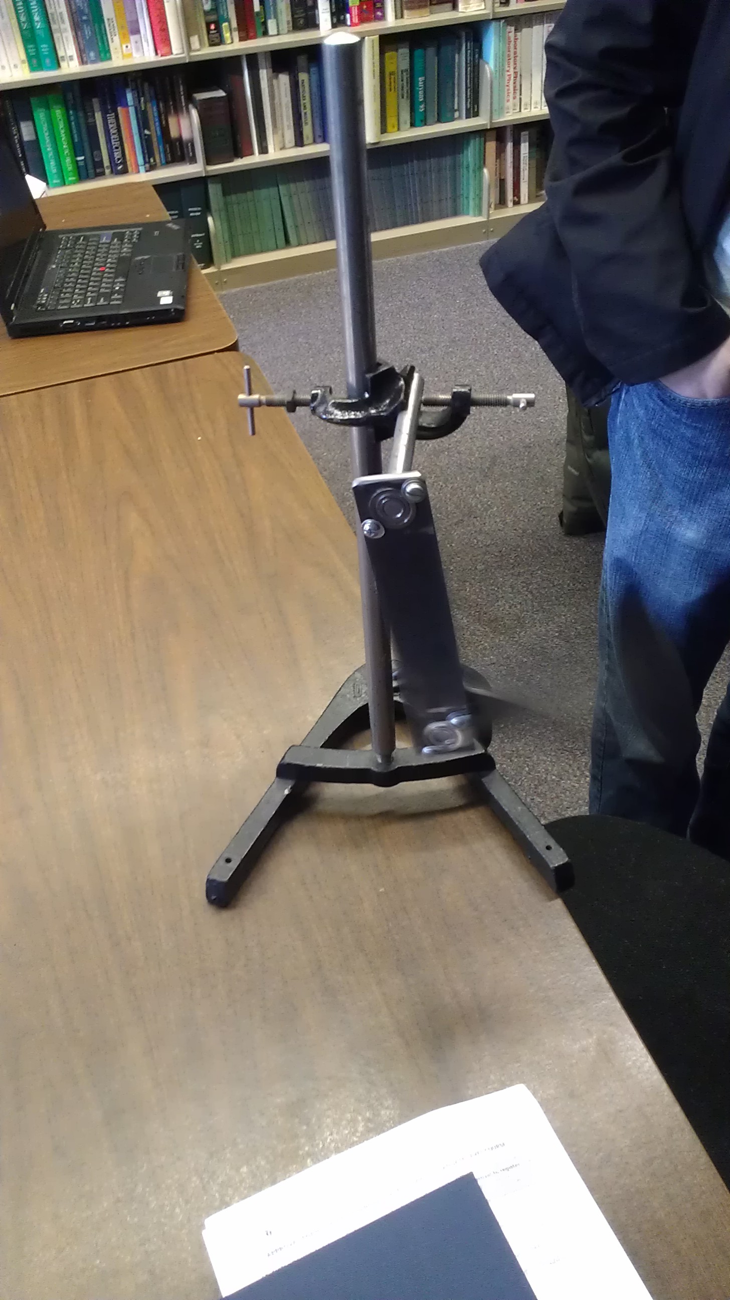
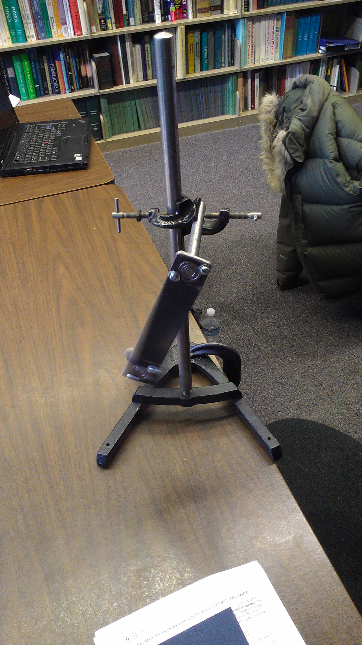
This Project outlines the simple construction of a fascinating dynamical system; a double pendulum or Chaos Pendulum. This project aims at creating a simple, cost effective and sturdy chaos pendulum for the RPI Society of Physics Students.
Processes Applied:


Summary:
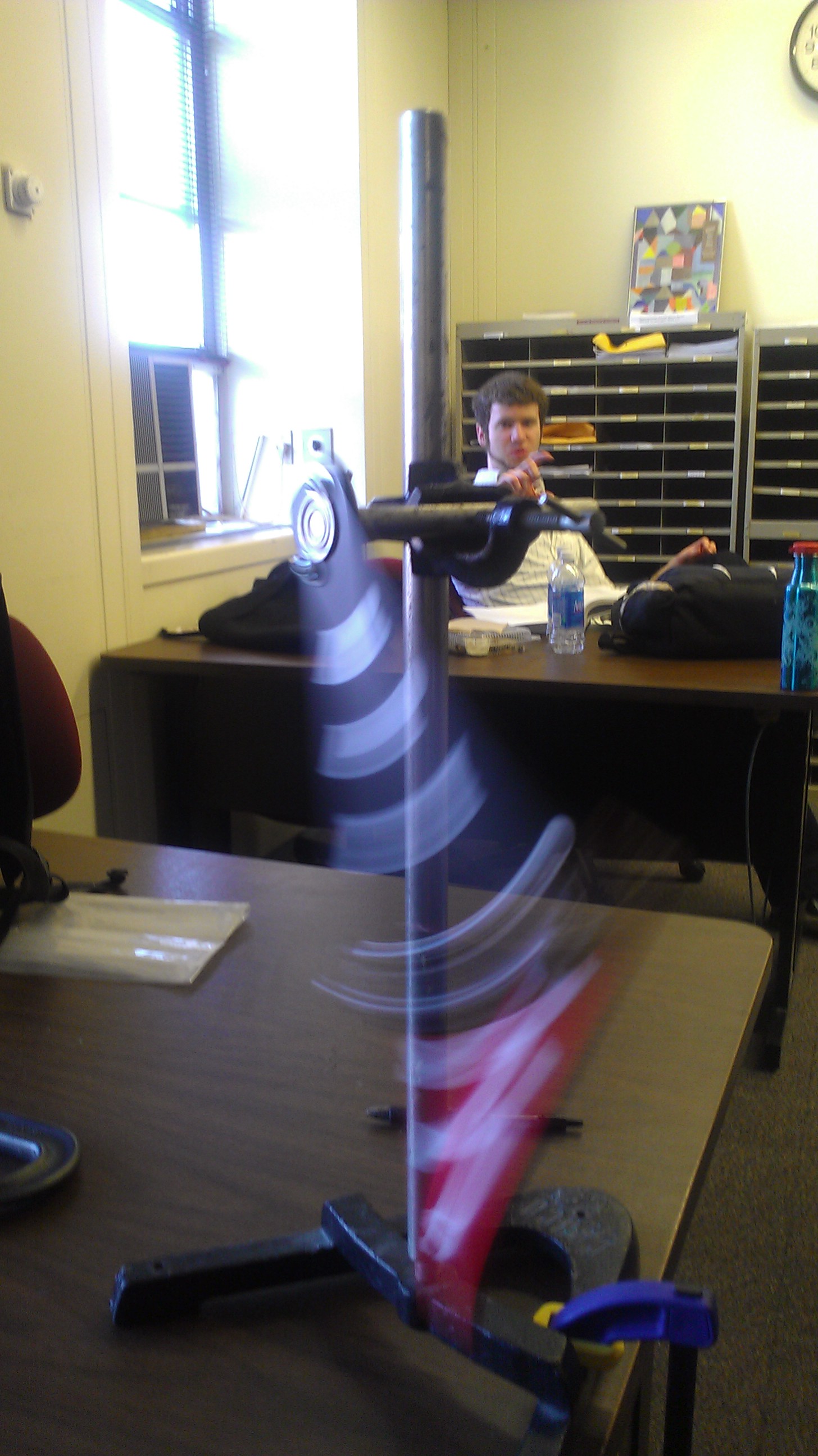
This project was aimed to create a model of a double pendulum for the RPI Society of Physics Students (SPS). The aim of this model is to be able to demonstrate the physics of an oscillating system, specifically a chaos pendulum. This model will be used to demonstrate to physics students the physical representation of the differential equations they must solve for a coupled system like this double pendulum. Another instance this model will be used for is to demonstrate the physics to high school students who do not have experience with the differential equations that govern the motion of this coupled system.
In the early stages of this project, I chose to use steel over aluminum because of its weight and durability against physical damage. The reason I chose steel over aluminum is that aluminum is prone to being 'dinged' up and this project is going to be in many situations where it has the potential of being damaged easily. Another consideration was the components I used to couple the pendulums, and this was a simple decision because I was able to acquire a handful of ball bearings from the physics dept. since this was a project for the physics sponsored club (SPS).
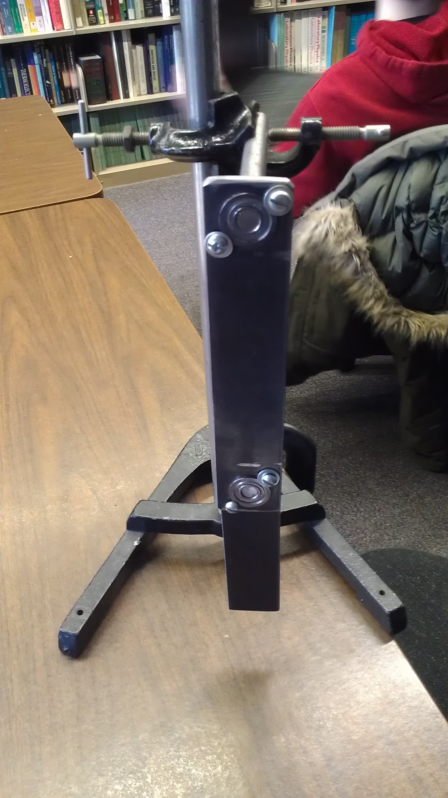
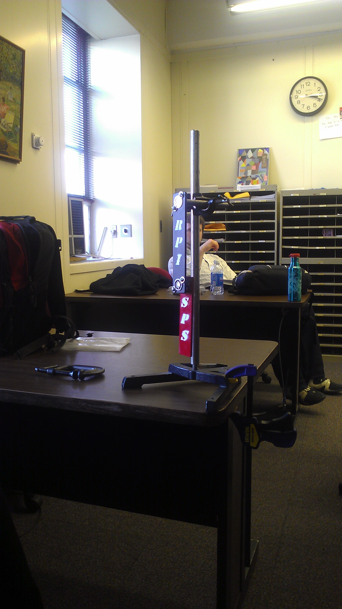
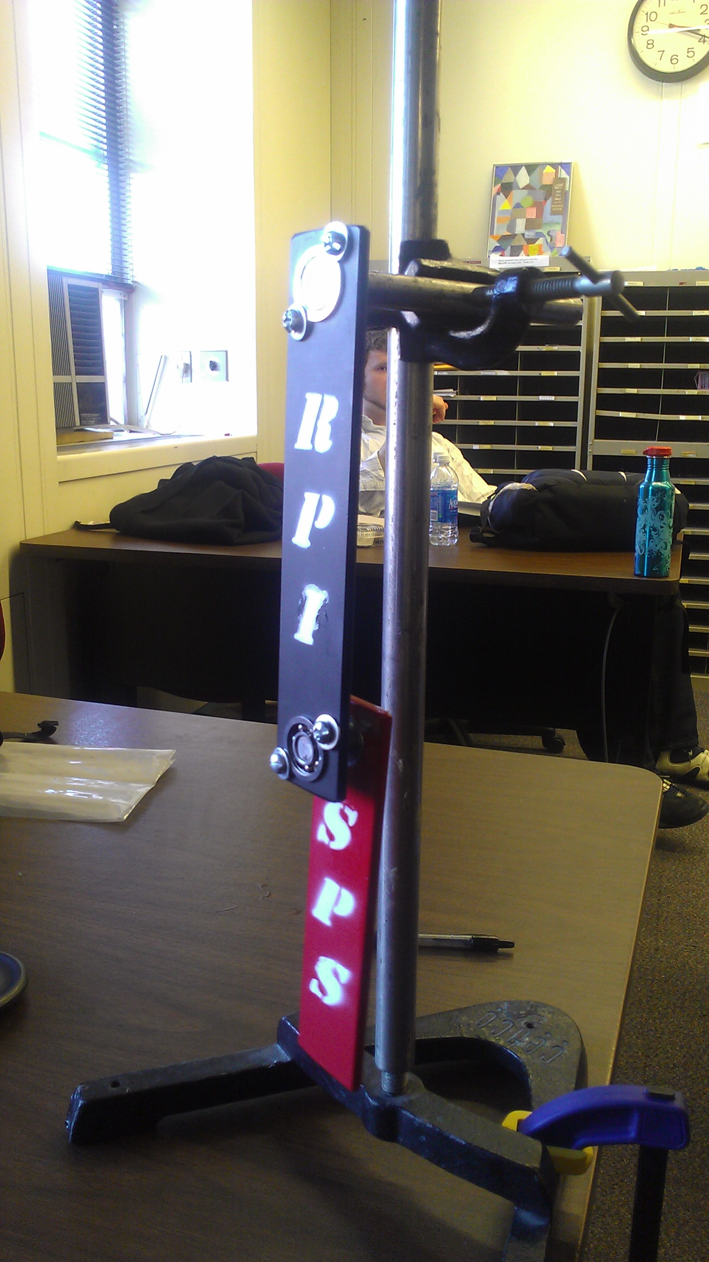
For the machining of this project, I first cut my two different pendulums using a Horizontal Band saw; The Lengths of the two vary. The variance of the lengths is a result of my attempt to create a large pendulum that is as stable as possible, meaning I needed to mount it so that it would not shake when in motion. This was partially achieved by this effort, but not entirely. The next step was to drill my holes for the ball bearings to be placed in my pendulums. The larger arm required to have two holes, while the smaller was my secondary arm which only needed one hole. For the holes, I aimed to drill them as close to the ends as possible given the material I chose (Steel). The closer to the ends the hole was drilled, more length of the arm is used in the motion of the pendulum. Also, it is important to note how thick of a barrier you leave when drilling because depending on the material you have chosen it could lead to an eventual failure in your pendulum (it could break and your bearing stops working properly). The holes for the bearings were drilled to the exact diameter of the inner of the two outer edges. This allowed for a snug fit when placing my bearings but also required me to secure them tightly with screws. I fitted two screws for every bearing to make sure that it doesn't slip out (better safe than sorry when you have steel flying around chaotically). The final component that was needed for this project was the steel arms, these are the components that connect the bearings to one another and the bearings to the mount. I used steel again for this part, specifically cylindrical stock which I machined down to the exact inner diameter of the bearings used. This allowed me to fit the arms into the bearings loosely. Next, I knurled the ends of the pieces of steel, this allowed for the outer diameter of the stock to be increased slightly to create a tight fit in the hole. Once everything was assembled, it was decided to spray paint the arms with Rust-Oleum and then stencil RPI SPS onto them.
In the end, I was able to create this project with $1 because of the donation of the Stand, C-Clamp, and Bearings from the physics department, but this cost would increase to around $50 because of the price of bearings. In the future I will look into using metric bearings due to cost.